Extras
Things
like the router mount, the work surface, dust collection, and Estop and Home Switches. Topics that aren't covered
anywhere else.
The Router Mount
I
was originally planning on buying a mount for the Bosch Colt trim
router that I bought for this project. There are at least two sources,
Probotix sell a a mount for the V90 and MCPI also sells a
mount. However a friend posted .dxf
drawings for one on the Fireball CNC yahoo group site, based
on reading the BritishIdeas Blog. (Scroll down to the Rigid 2400 entry). I
thought I'd try my hand at making my own first.
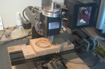
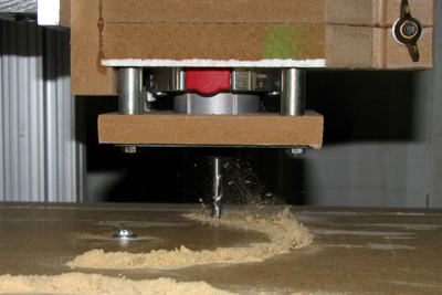
Here the outer edges of the raw blank have already
been machined away
and I'm cutting the mounting hole for the router. Note the screw that's
holding down the center part of the circle to keep it from coming loose
at the end of the cut. |
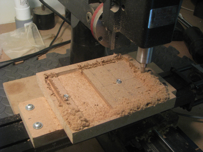
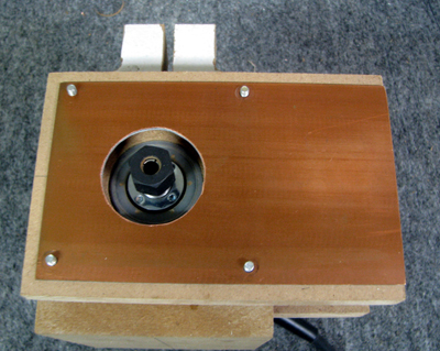
This
is the back of the mount. The part that you bolt to the Z axis plate.
The pocket has already been cut and the outer edges are being trimmed
off. |
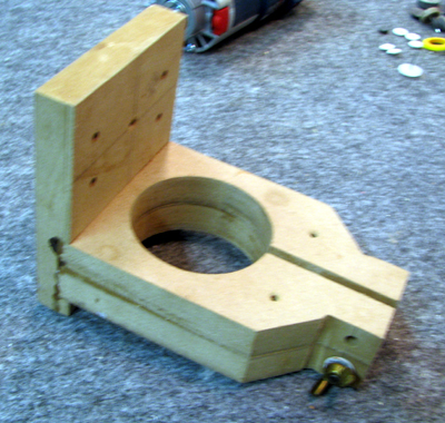 |
Here is the
mount glued together. You
can see it with the router installed in the assembly section. Consider
this as version 1. Based on some postings on the fireball cnc forum and
my limited experience using the router I'm
going to have to add a dust collection fixture to the mount.
See the entry below on Dust Collection for a
revised version of this mount!
|
Gotcha's:
(1) I had to cut two pieces for the part of the mount
that
holds the Colt. I'm cutting the first one in the picture above. Note
the machining order. I trimmed the outside first, then I cut the
circular part free and cut the slot between the 'jaws' of the mount.
Those were two separate gcode files. I made the mistake of
reversing the cutting order when I cut the second piece. The
circle & slot gcode was already loaded so I figured why not. I
must
have been tired. Really tired. The effect of cutting the circle is to
remove the anchor from the left end of the piece of stock. There's
nothing holding it down when you go to do the trim cut. That's 3/4 inch
MDF and it's amazing how much it can flex!
(2)
Glue the two jaws together before you cut the back of the mount. That
way you can make sure that they fit into the slot you are cutting in
the back piece.
The Work Surface
CNC
routers wind up with lots of work surfaces stacked one on top of the
other. At the bottom of the heap is the nice sturdy, stable, heavy duty
one that you really don't want to cut into. On top of it are a variety
of work holding fixtures and sacrificial surfaces that allow you to cut
all the way thru the work piece without damaging the real work surface
underneath. This accumulation of surfaces is a
double edged
sword. The closer you can bring your work piece to the bottom of the
router the better. Closer means there will be less flexing and better
accuracy. But eating up too much space means the size of the workpiece
will be restricted.
Folks
have used lots of material for their work surfaces. MDF is typical but
I've seen aluminum plate, 80/20 extrusions and corian among the choices
folks have made. I decided on MDF as the low cost option, figuring I
could upgrade later on if it proved to be inadequate. Two
posts, from the fireballcnc forum, prompted my choices of the
worksurface design. Table Flatness
convinced me that I should use two layers of MDF. T-Nuts
is a good explanation of how to use them and convinced me that they
would be a better alternative than insert nuts. Based on those two
posts, I decided on a work surface using two sheets of 1/2" MDF.
I came up with three options for mounting the work surface.
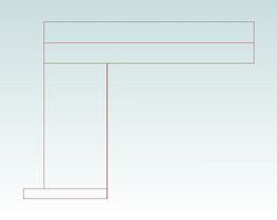
1 - The conventional mounting |
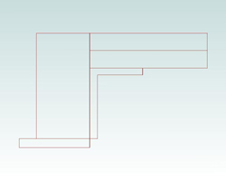
2 - Using an angle bracket to save working height |

3 - Recessed bottom layer with extended top |
The conventional mount would cost 1 inch of working height.
The Angle bracket mount would save that height at the expense of
additional parts and a more complicated alignment for the top.
Recessing the bottom layer saves 1/2 inch with no added expense.
Extending the top over the base rail shields the rail from some of the
dust and debris generated by the router. I used the third option
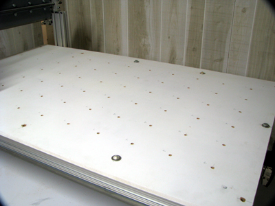
The router was used to 'drill' the bolt holes in the top. | 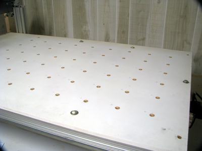
And then a V bit was used to countersink the bolt heads |
The recessed layer was then drilled and spot faced | 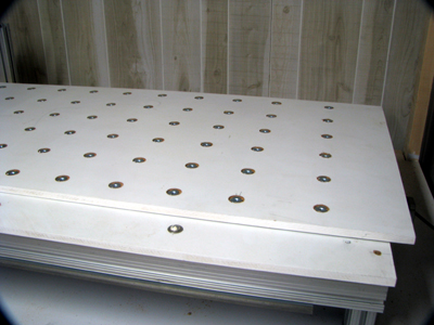
And the Tee Nuts were installed |
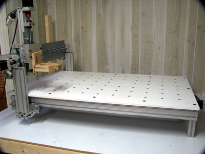
The finished work surface.
The mounting holes around the edges were also countersunk
Right: The work surface overhangs the bearings to protect
them from debris | 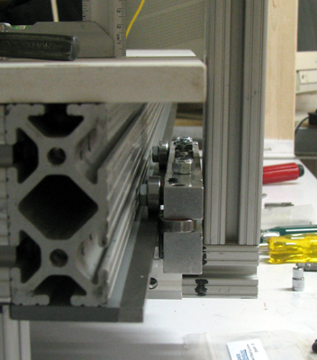 |
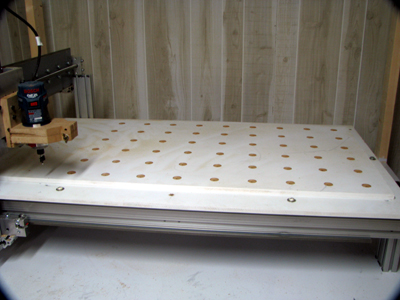
So, It turns out that it's a really Bad Idea
to have the work surface overhang table. While it can protect the
bearings from dust, It also makes it impossible to get a wrench in if
you have to adjust the carriage. I wound up removing the top and
cutting off the overhang.
To the right you can see the modified work surface with a wrench in place for carriage adjustments. | 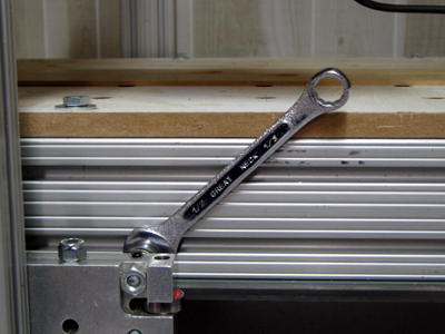 |
Dust Collection
The
first thing I used my new router mount for was to cut the holes in the
work surface for the tee nuts. Dust and chips from the MDF got
everywhere even though I was holding a vacuum intake hose right next to
the router bit. I
remembered a post in the Fireball CNC forum "Dust
Revisited".
The downdraft from the router cooling air was blowing the dust away
before the vacuum could suck it up. Using the idea's there I
re-designed the Bosch Colt mount (above) and added a
combination exhaust deflector and dust collector/vacuum boot.
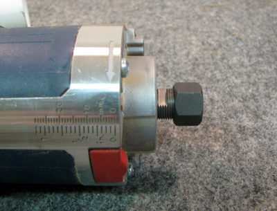
This is the Business end of the Colt Router.
Because of the uneven profile, there's no convenient place to mount a downdraft deflector | 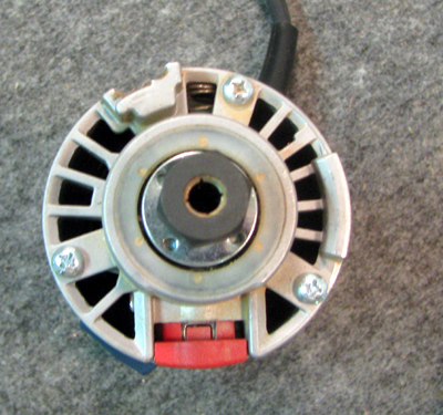 |
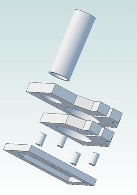 | I modified the original Bosch Colt mount by attaching a combination downdraft deflector and vacuum
intake to the original mount. Not shown are four pieces of threaded rod
that hold the assembly together (see below). The spacers are 7/8 inch,
designed to leave enough space to fit a finger into the mount to engage
the spindle lock when changing bits.
The bottom is sealed with a thin sheet. I was going to use some plastic
but didn't have any so I cut a piece of printed circuit board laminate
that I had handy.
You can look at a 3D PDF model of the mount.
You can download .dwg and .dxf files for the version 2 mount. |
The Colt is a tight fit into the hole in the dust catcher. | 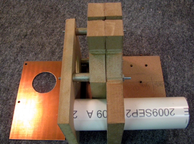 |
 | 
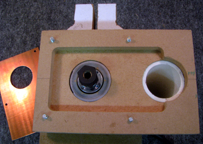
This
pix was taken during my first test cut. notice the tornado of dust
flying up into the intake. Yes some was left behind on the work surface
but at least it stayed put. It was mostly in the slot that was being
cut and was easy enough to vacuum up when the cut was over. |
eStop and Home
Switches
I
went on-line to find a source for an inexpensive eStop switch.
Experience with my Sherline 2000 mill has shown me that I'm not fast
enough going to use my keyboard to stop the mill when there's a
problem.
When I found a source for the eStop switch I also found a supplier for
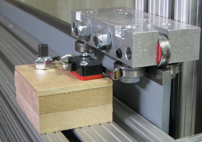
home/limit switches so I bought some to use on this router as well. Figuring
out how to mount them was a little bit of a challenge. It's important
that the switch not be damaged by overtravel. Sometimes it's
convenient to be able to move the carriage beyond the switch without
having to remove the switches.
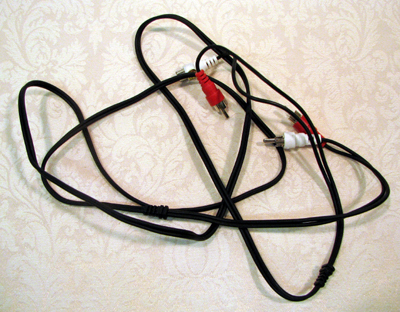
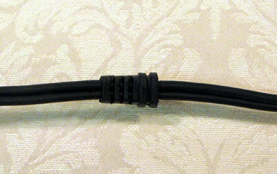
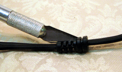
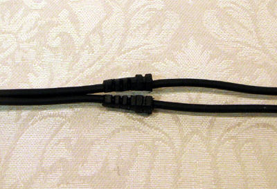
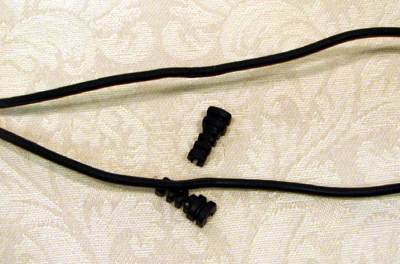
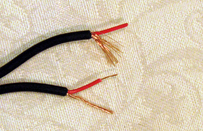
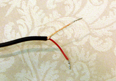
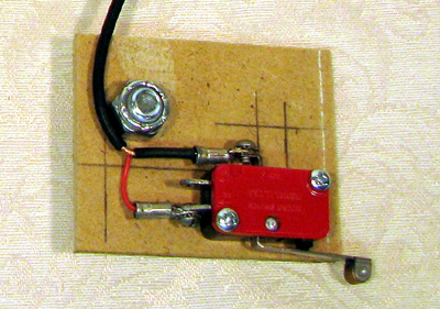
For
the home switch and eStop switch wiring I used stereo audio cables
with RCA phono plugs. These mate with the connectors I used on the
electronics enclosure. They are cheap, and the stereo pair is easy to
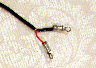
separate into single cables. I put terminal lugs on the ends of the
cables I used on the limit switches with shrink insulation on the bare
ground wire since it's close to the other switch contact.
 |  |
 |  |
 |  |
 |  |
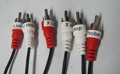 | Make sure you label the ends of the limit switch cables. |
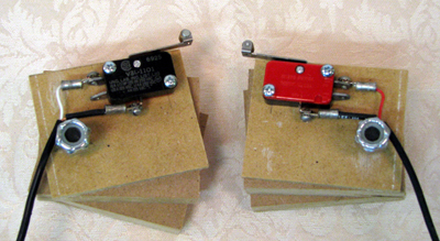
The Home switches were easier to mount than I had originally expected. I made a small mounting
plate out of 1/8 inch thick paneling and them bolted the plate in place
using the same type of carriage bolts that are used througout the
router build. This worked easily for the X-axis. In order to use the
same mounting technique for the Y-axis I made 1 inch spacer blocks to
position the switches correctly. You can download .dwg and .dxf files
for the switch mounting plate. The switches are Micro Switch V3L-1101
series. A .pdf data sheet is included with the mounting plate drawings.
 | 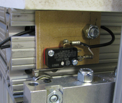 |
 | 
I have since moved this switch to the underside of the beam
Where it's more out of the way. |
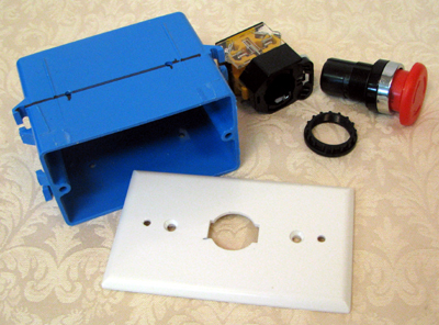
The
eStop switch is mounted on a standard switch cover plate and then
installed in a standard outlet box. There are a wide variety of
switches on the market. This one, purchased on eBay, appears to be
chinese in manufacture see the Jiangyin Changjiang Electronic Appliance Co. web site.
The only markings I could find were LA23/203/209B. It mounts in a
22.5mm hole and the mushroom top is 38mm in diameter. A really nice
switch for the price! The cover plate drawing is included with the micro switch mounting files above.
 | 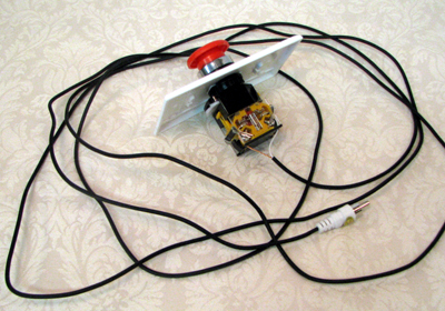
I used the same kind of audio cable with RCA phono
plugs as with the limit switches |
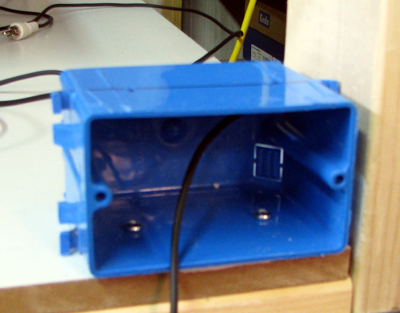 | Holes were drilled in the sides of the outlet box for
mounting. The cover plate is oversized and hides
the nail mounting flanges on the ends of the box. |