What
Speed
Now that I think my machine is mechanically aligned, how fast should I make it go?
It's not an easy
question. Cutting speeds are determined by the material being machined,
the cutter (diameter, number of flutes and rpm) and sometimes the path
being machined (rough cut vs finish cut). Jogs, or rapids, are moves
made when not cutting. Those ought to be made as quickly as possible
since they represent wasted time. The question is how fast is fast?
That's determined both by the computer and software driving the stepper
motors as well as the mechanics of the system. There is no
strightfoward answer. You need to start somewhere conservative and then
increase your limits until something stops working. There are two
factors at play. One is the maximum speed you can go at. How many steps
per minute can your computer reliably generate. That number, divided by
the number of steps/inch for your system gives you your maximum inches
per minute. The problem is really not how fast you can go, but how fast
can you accelerate to that speed.
So how do you measure your systems speed and acceleration? You don't. You measure a starting position, you "move around a lot",
and then you return to your starting position. If you wind up back
where you started out then you are running accurately. If that's the
case, you increase the speed and or acceleration (only make one change
at a time) and try again. You keep doing that till you encounter
position errors. Then you reduce back to a lower value to give you a
safety margin.
Here is how I mounted a cheap dial indicator onto my system to make position readings.
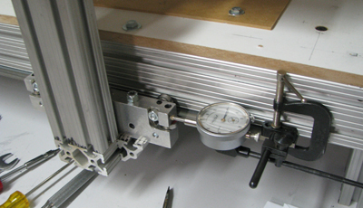
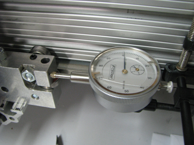
This is setup at the far end of my X travel. A closeup of the
Dial indicator showing .001 position error is to the left.
That's within the backlash of the Lovejoy couplings I used.
|
|
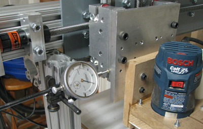
This is my setup for the Y axis. One drawback to this setup is
that the indicator has to be moved out of position whenever you
home the y-axis.
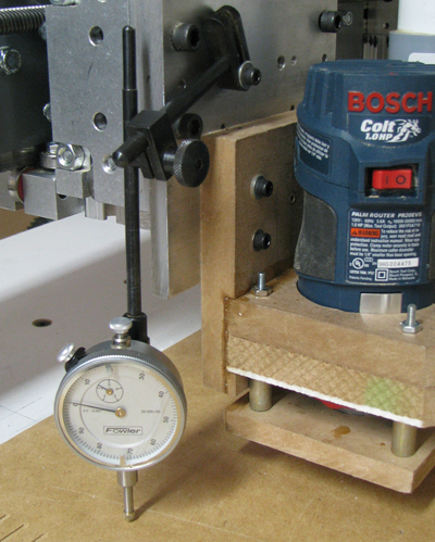
To the left is the setup used to test the z-axis
|
|
So the real heart
of testing is the g-code that supplies the "move around a lot" action.
The code I used is derived from a sample provided in the EMC2 User's
guide.
The heart of the program is a simple loop. For the X-axis it looks like:
o100 repeat [#<axcount>] ----- number of times to repeat the loop
G0 x[#<pstart>] ----- rapid to the starting position
G4 P0.10 ----- delay for .1 second
G0 x[#<pstop>] ----- rapid to ending position
G4 P0.10 ----- another delay
o100 endrepeat
The
comments (---- above) are not part of the g-code and the variables need
to be set to determine where start and stop actually are. The actual
g-code also
has a move to a test location where you set up your dial indicator and
zero it. You don't want to be hitting the the indicator on each pass of
the test so I typically put that .5 inch away from the range of the
test (distance from start to stop is the test range). There are
actually two copies of the loop with a measurement at beginning, middle
and end. The first loop has the delays in it. That loop tests the
machine's acceleration and velocity settings. The second loop has no
delays. That loop runs much faster and tests the max acceleration
settings and driver setup and hold times for your software. I've
prepared a .zip file that has copies of the x,y and z axis tests as
well as some other useful g-code for you to download.