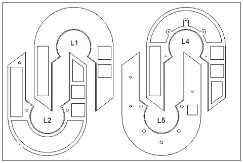
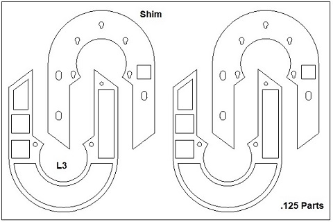
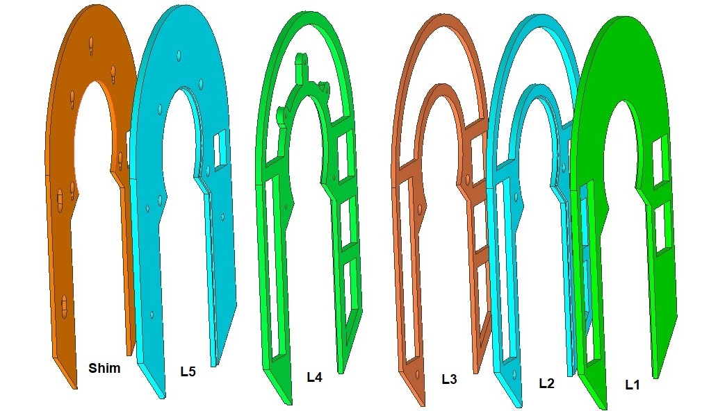
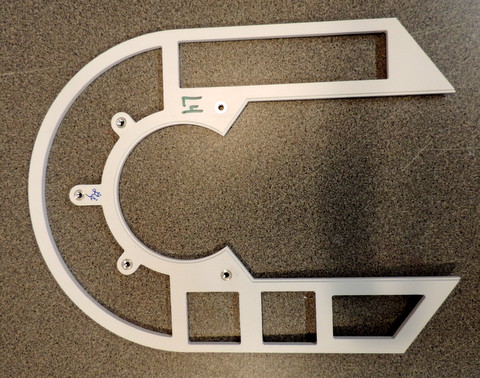
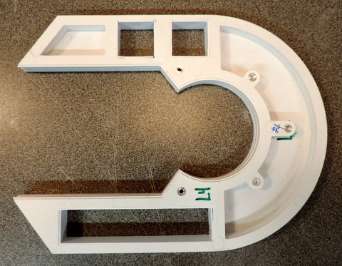
Assembling the Layers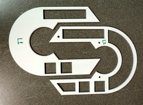
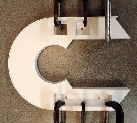
Begin with Layers #1 & 2 - make sure the channel is in the center and the cutouts in the parts line up. |
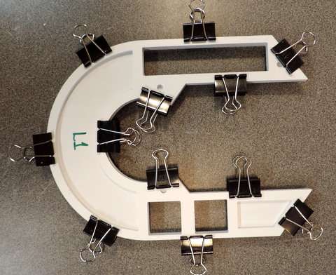
I've used spring clips (aka binder clips) - C-clamps might have been a better choice.
|
|
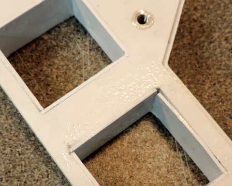
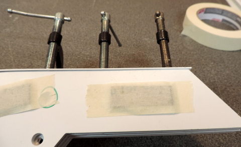
Left: Make sure the corners line up. Once the alignment is OK use Weldon #3 cement to join the parts. 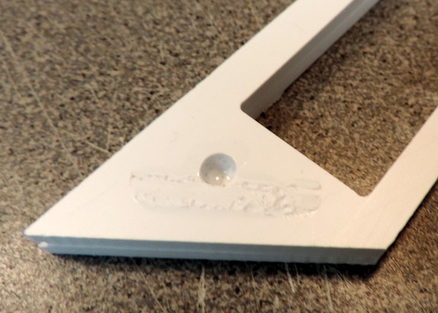
The hole above is a glue point - try not to overfill it. |
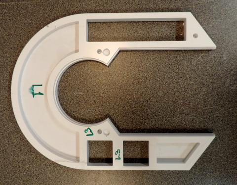
Once the cement on the first 2 layers has set, add layer 3. 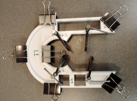 |
 |
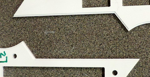
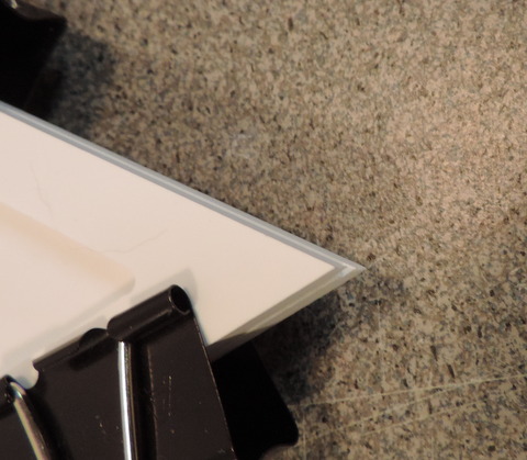
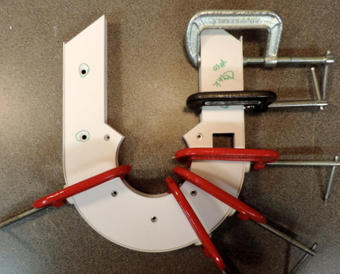
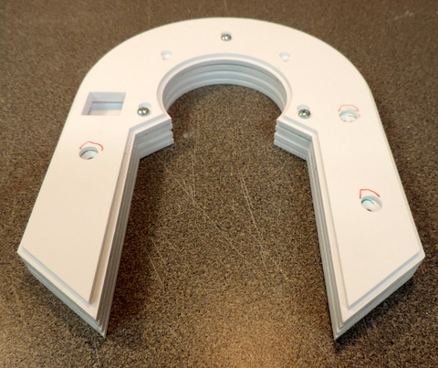
This is what happens when you get sloppy with the
cement! It's hard to see, but the red V's point to places where the
cement got under the spring clips and caused the plastic to melt. -
If it happens to you be sure to sand down the ridges!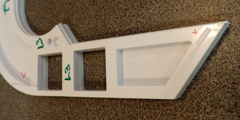
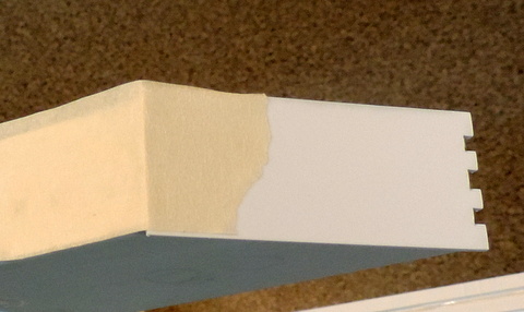
Right:
I've added the Nutserts to layer #4 - that part will be supplied with
the Nutserts installed unless you ask me to leave them out. |
 |
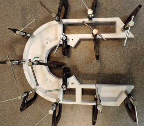 |
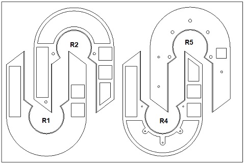
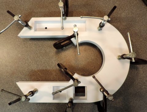
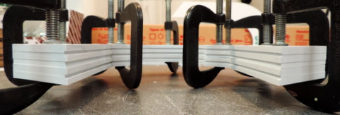
Left: you'll need lots of clamps to hold both the inside and outside layers together. 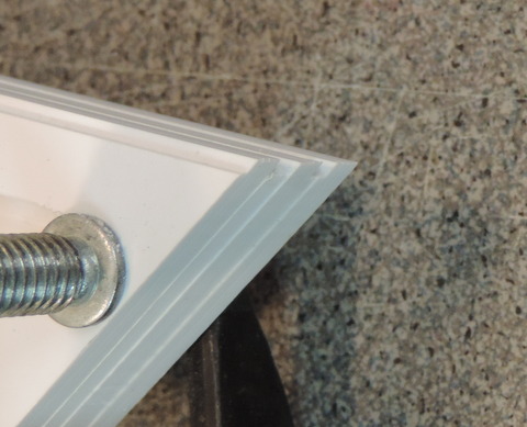 |
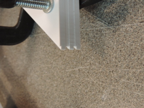 |
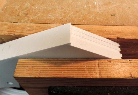
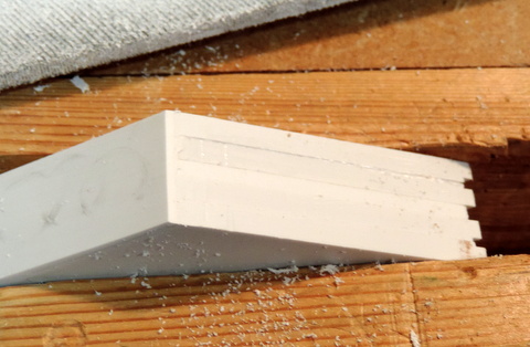
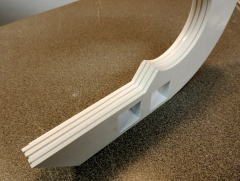
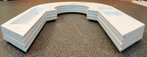
Above, Left & Below: Alignment of the layers where the
points come together is critical because of the visibility. Because of
the channels cut into the parts it's not possible to trim them back
without reducing the channel depth. |
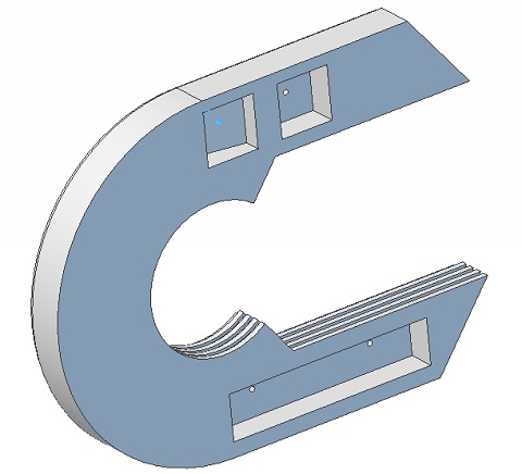
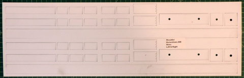
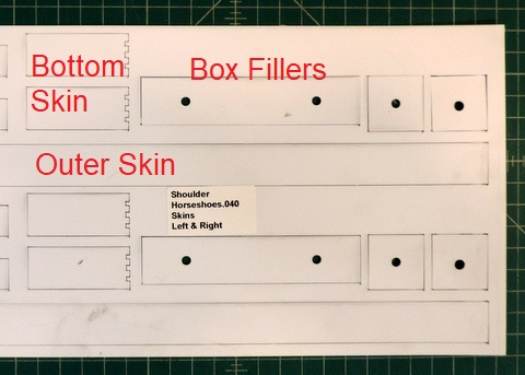
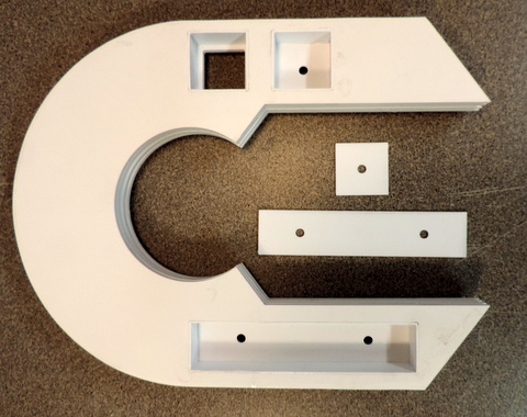
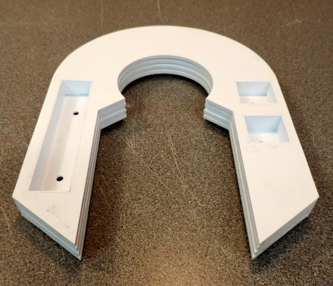
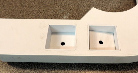
Lining the Boxes
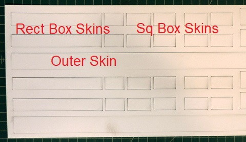
One
of the drawbacks to using multiple layers for the construction of the
horseshoes is that the layer joints are visible and difficult to cover
up during the finishing/painting process. My solution is to glue small
pieces of .040 to the inside of the boxes (cutouts) as well as to the
outer edge, |
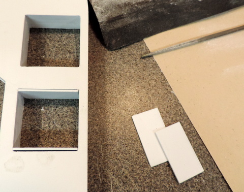
there
are sets of parts for all 3 of the cutouts. note that for the square
cutouts the pieces are two different lengths - two slightly longer than
the other two. All of the pieces are oversize in height and will be trimmed down after they are glued in place. |
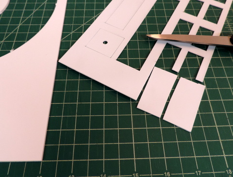 |
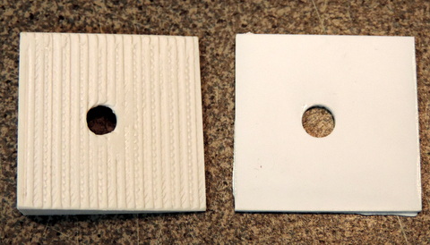
Left: If you haven't glued thin .040 stock now is the time to try with some scrap pieces. Cut some pieces from the scrap.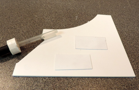
And see what happens when you apply cement. |
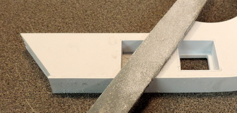
Below - The corners of the cutouts are slightly rounded.
Use a file with a 'dead' edge (no teeth - so it only removes
material in one direction) to sharpen up the corners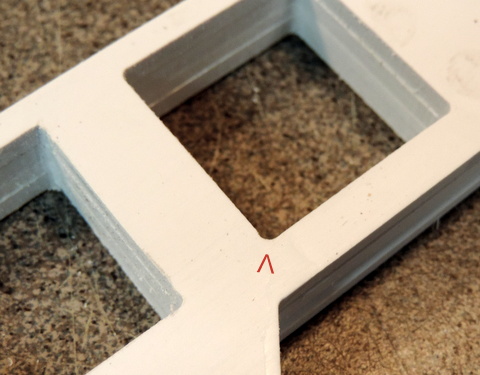 |
After just a little filing!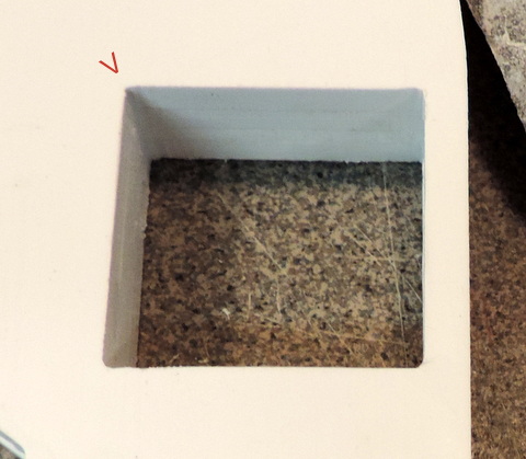 |
 |
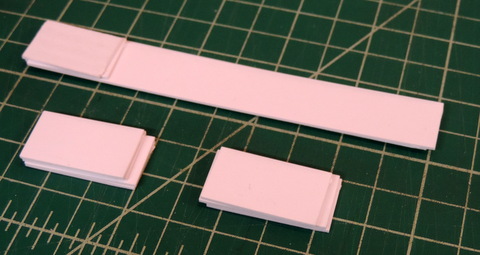
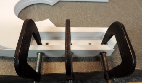
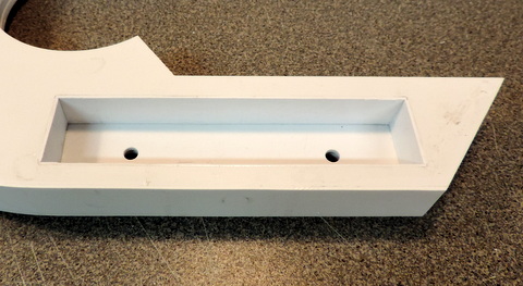
Left: test fit the pieces. For the sq cutouts start with the
longer pieces. Sand the end down (if necessary) until the piece just
fits. 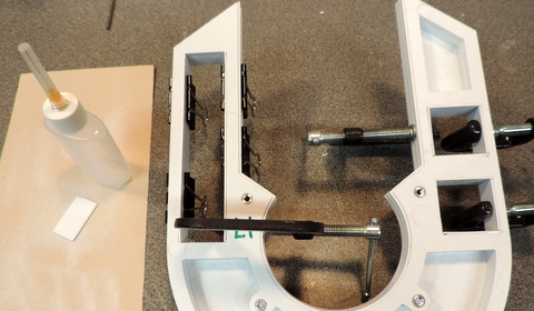
Clamp
the pieces in place and apply cement. Note the bottle with the hypo
needle. Repeat the process for all of the cutout edges. |
 |
 |
I'm using a large coarse file to remove the edges of the box
liners that stick up above the edge of the cutouts. When filing hold
the file almost flat to the surface so the finished edge is square to
the surface. 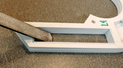 |
 |
Not my best work, but this is the bottom of the cutout and won't be visible. |
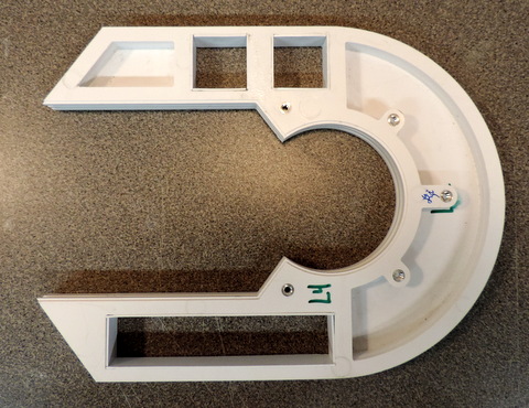
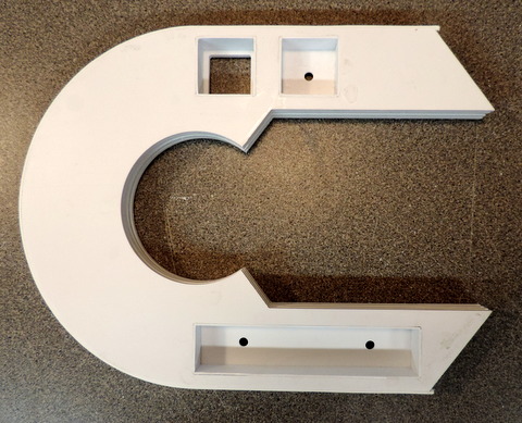
With the Top & Bottom edges of the cutout filed level it's time to attach Layer 5 to the bottom of the Horseshoe. |
 |
 |
| Above & Right: as with the other layers, alignment is critical! Once you put the cement on it's too late! |
 |
Gluing on the Outer Skin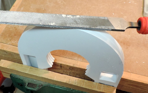
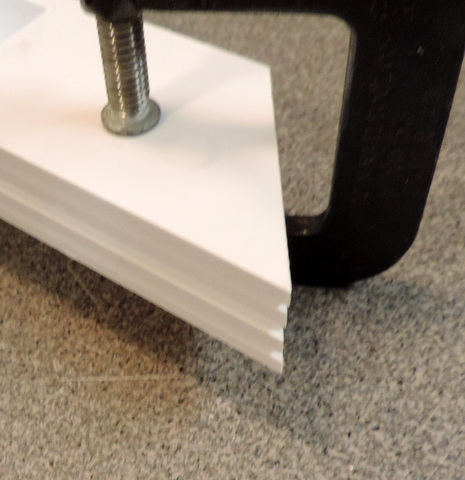
Gently
File down any high spots - be careful not to put a flat spot on
the edges. Right - place thin cardboard spacers on the underside
- tape in place. | 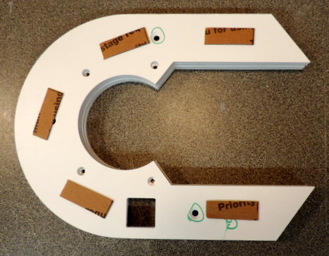 |
Start at the bottom edge. Extend the strip over the end. |
The spacers enable ~equal edge overlap on both top & bottom. |
Clamp Down the other end. Make sure it also extends over the end. Make sure skin is tight on the curved section - Apply cement. |
With
20/20 hindsight I should have taken out the bigger clamps and used them
on the curve when I glued the first time. In any case if there are sections
that are not tight clamp & glue again! |
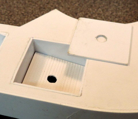
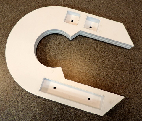
 | As a result of the layer structure at this point the cutouts are too deep. The spec calls for .65 in depth.
The layering (3x .1875 + .125) results in a depth of .6875
which is .0375 too deep.
I've provided .040 pieces to bring the depth closer to spec.
Their use is optional.
The 3D printed Wedge has been adjusted so that it's finished height, including the .040 surface layer brings it to spec height. |
Trimming the Edges of the Skin
work very slowly, with the file held almost level, and only pushing against the horseshoe, file down the edge of the skin. |
Check the remaining edge with your finger after every few strokes. Work your way around the horseshoe. 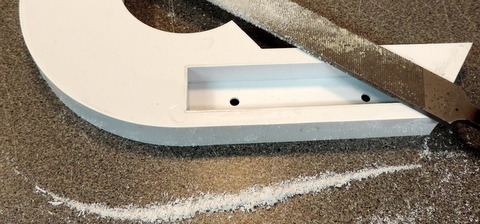 |
 |
Repeat the process for the edge on the reverse side.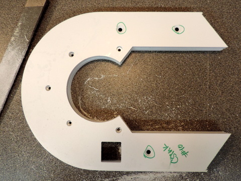 |
|
This
shows the outer edge trimmed before the bottom trim is added (below) -
or you can wait until after the bottom trim is in place. |
 | Left: There's a pair of Bottom Skin .040 pieces that have
a notched end to match the notches in the horseshoe. These cover the
layering on the bottom edges. Since it's just about impossible to clamp
these in place, rely on masking tape (add more to hold all 4 edges).
Use a glue bottle with a hypo needle to put drops of glue on the
overhanging edges. |
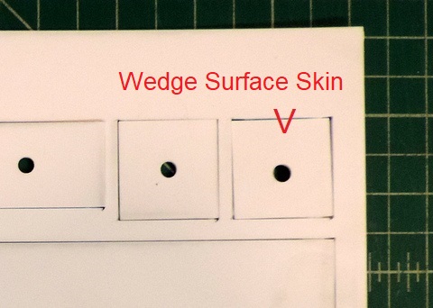
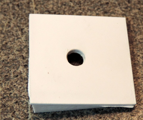
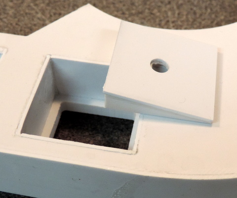
Above: the 3d printed wedge's surface is quite rough. while it can be sanded smooth it's easier to glue a piece of .040 on top
Right: like the other pieces of .040 the wedge edges will have to be sanded to fit the cutout.
| 
|
The
wedge is square - there are 4 ways to put it in the cutout. 3 are
WRONG! Make sure the wide part of the wedge is at the bottom of the
cutout.
|  |
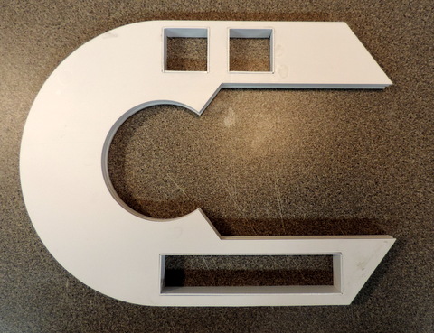
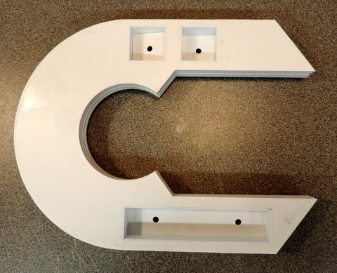
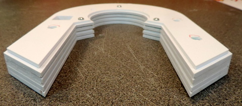
Assembled Horseshoe - ready for finishing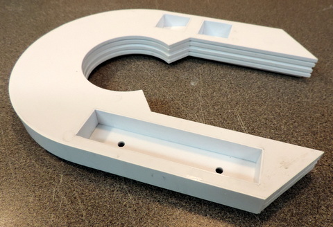 |
 |
 |
 |
|
|
 |
 |
 |
 |
 |
 |
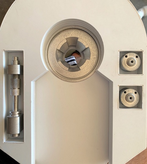
| Thanks
to R2 Builder David Codding, here's a picture of my Shoulder Horseshoe
with 3D printed Shoulder Hydraulics, Shoulder Buttons and Shoulder Hub
installed!
You can find those parts on my 3D printed parts page:
http://www.r2-3d.media-conversions.net/
|