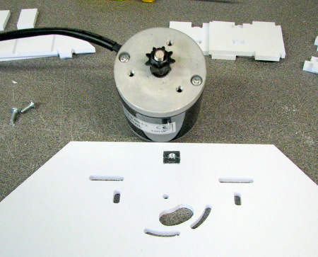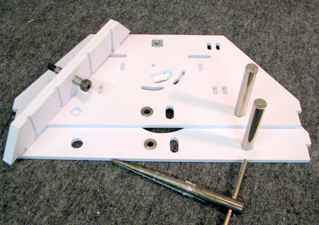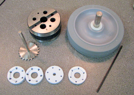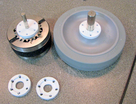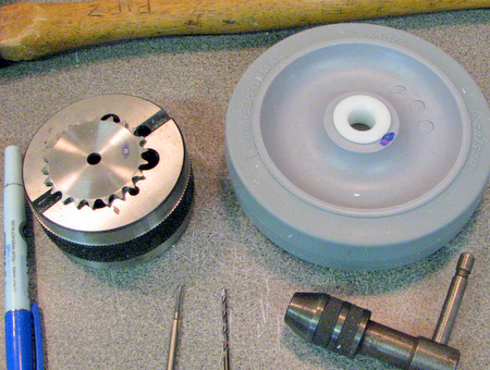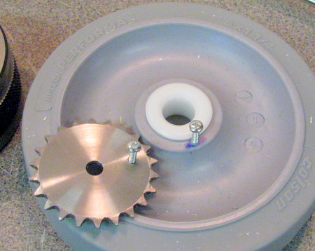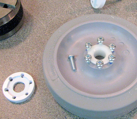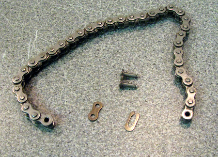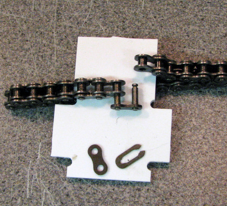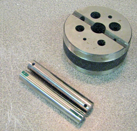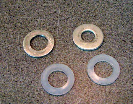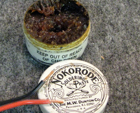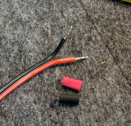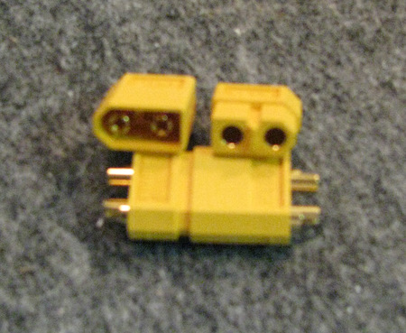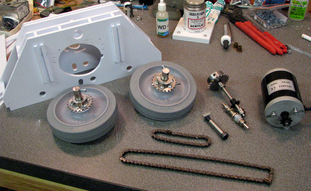
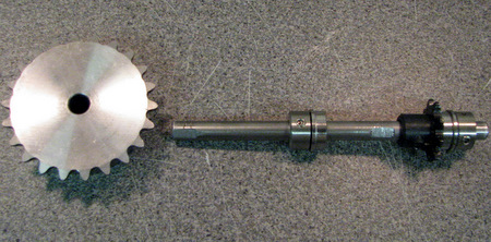
Above: The parts needed for these steps.
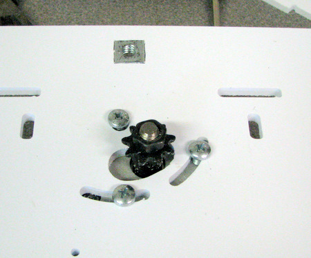
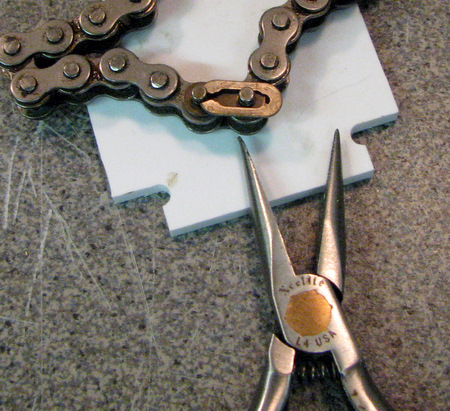
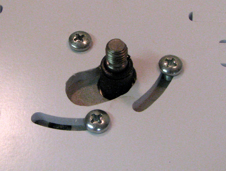
Right: you can use the shoulder bolt as a handle to
insert the square nut. |
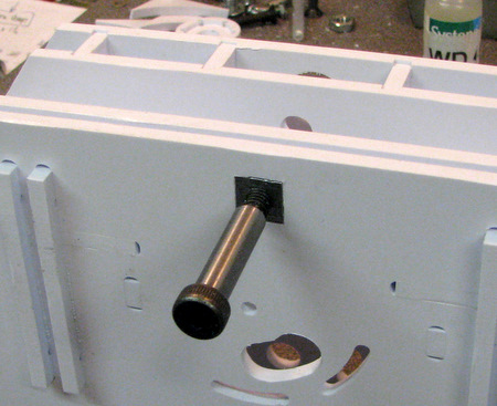 |
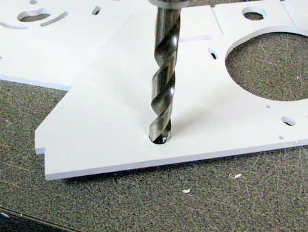
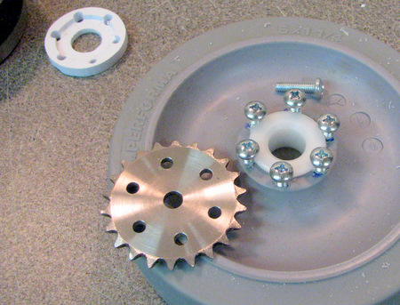
Check that the shoulder bolt fits the mounting holes
in the structural frame. Enlarge with a 3/8 drill if necessary. |
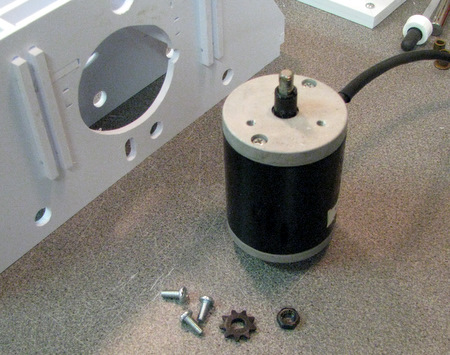
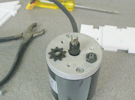
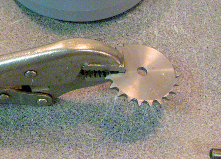
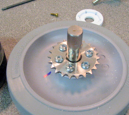
Remove the sprocket from the motor shaft. |
Mount the motor. [Not shown, re-install the sprocket!] |
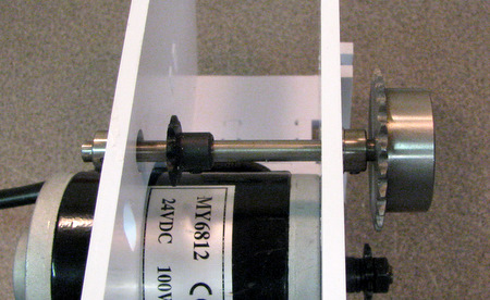
Install the jackshaft. Location of the 9 tooth
sprocket is approximate for the moment. |
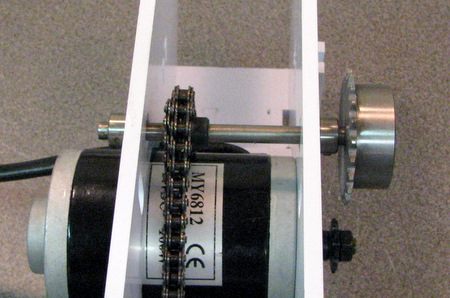
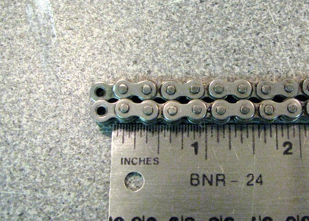
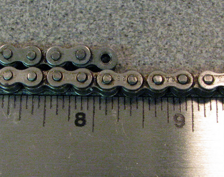
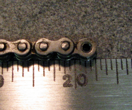
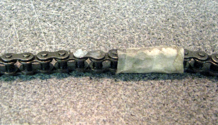
Above: Remember to install the 20 inch chain too!
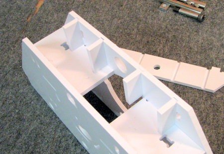
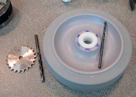
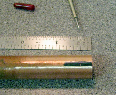
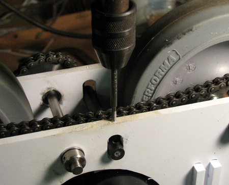
Right, and following, is the (new) chain tensioner
installation. Note the centerlines and punch marks for the drill holes.
|
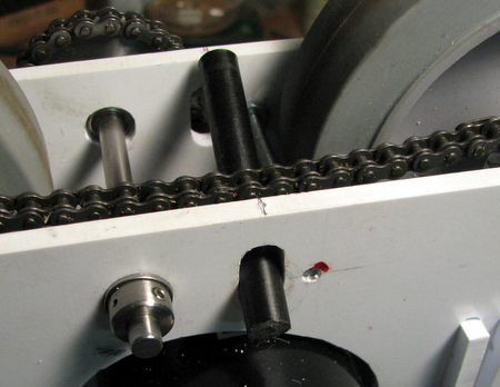
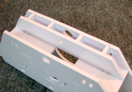
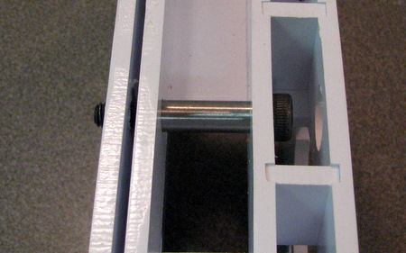
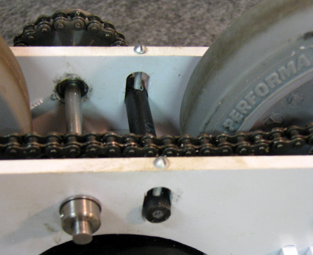
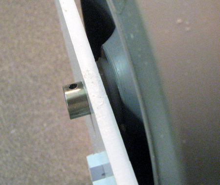
Either enlarge the slots, or lightly sand the Delrin
rod so that it easily slides up and down in the slots. |
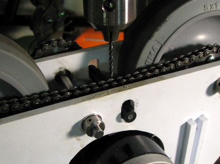
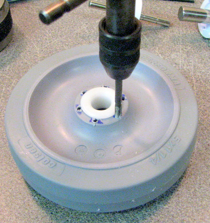
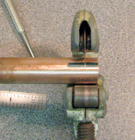
Drill threw the edge of the frame to tap a hole for a 4/40 bolt. |
While holding the tensioner rod, use the drill to
'dimple' the surface of the rod. It's not necessary to drill threw the
rod. |
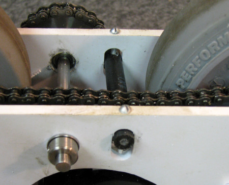
Tap the hole |
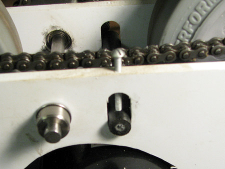
Install a bolt and use the end of the bolt, in the
'dimple' made previously to hold the tensioner rod in place. Repeat the
drill/dimple process on the other side. |
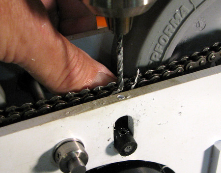
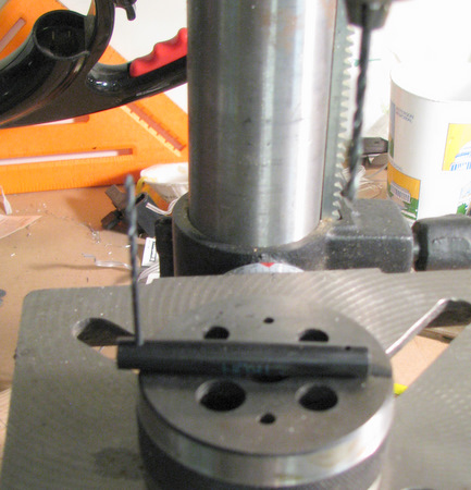 Remove the
tensioner rod and drill one dimple all the way threw using the tap
drill. Switch to the oversize drill and use the tap drill as a handle
to position the rod. Remove the
tensioner rod and drill one dimple all the way threw using the tap
drill. Switch to the oversize drill and use the tap drill as a handle
to position the rod. |
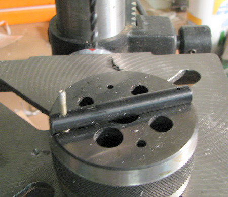
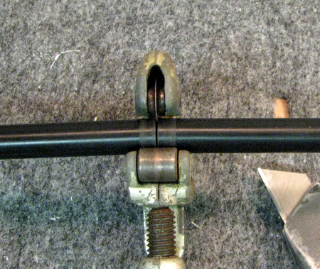
To align the rod while drilling the second
hole use a screw. The rod needs to slide
up/down smoothly on the screws.
|
re-install the rod to verify the smooth fit. |
 |
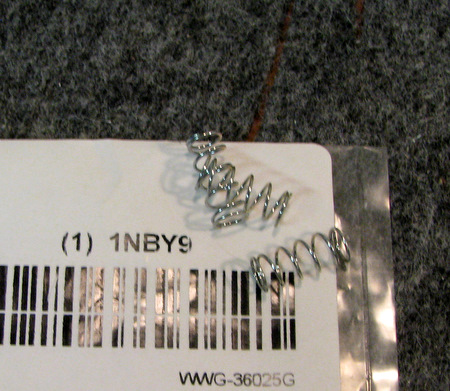 |
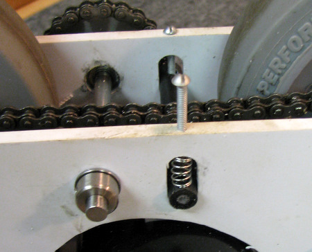
Install one spring on each side. |
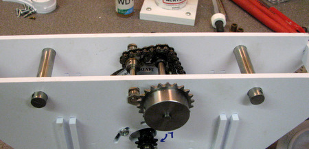
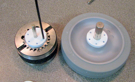
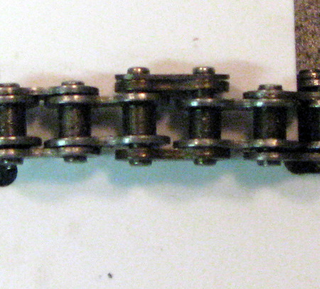
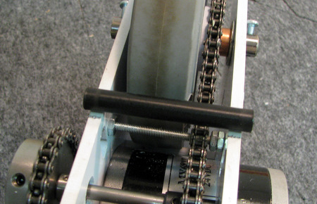
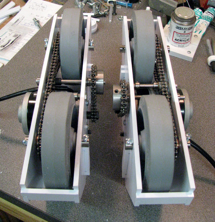
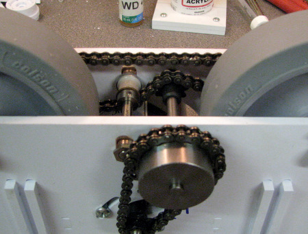
Verify the fit of the two wheel axles. Note that we have reverted
back to the old tensioner. Note the chain routing. It's
Above the 9 tooth sprocket and below the tensioner to give more "wrap"
to the chain around the small sprocket. |
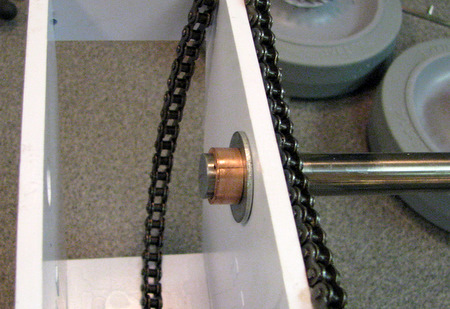
Above: Drape the chain so it's out of the way. Insert
axle shaft, add washer and spacer.
Right: slide wheel & sprocket assembly onto shaft.
|
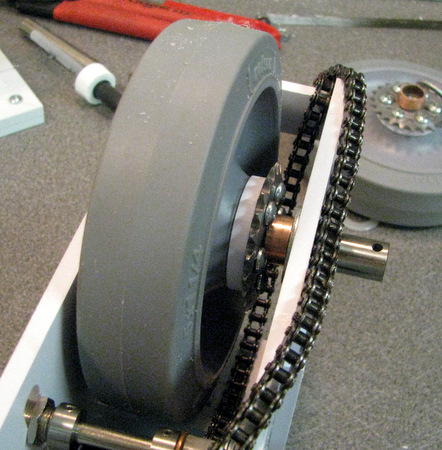 |
Add washer on the other side of the wheel.
|
slide axle threw second washer and use (bolt) hole to
secure axle
in place or install cotter pin |

Repeat the installation process for the other wheel |
Now that you know where the jackshaft sprockets
are located, mark them on the
shaft, disassemble the jackshaft and file flats on the shaft. Don't skip this step. If
the sprockets slip the set screws gouge the shaft and disassembly
becomes very difficult. Oh, and driving your Droid with one
drive 'slipping' is impossible. | 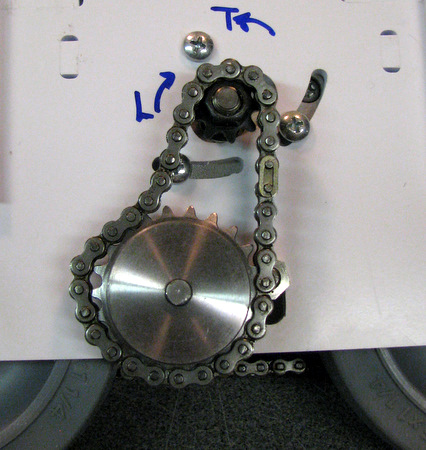
Loosen the motor mounting screws. Slip the chain over the sprockets |
Rotate the motor so the chain has no slack but don't make it overly
tight. Then tighten all 3 screws. |
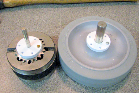
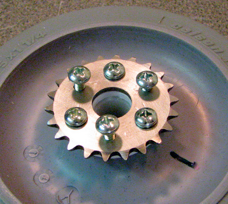
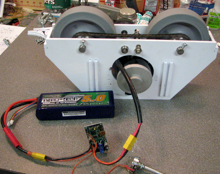
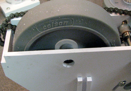
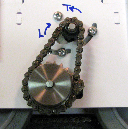
Finished outer drive wheel assembly. This
picture shows the
chain path over the sprocket under the (old style) tensioner. The
spring loaded tensioner should provide enough tension on the chain so
that it does not sag. |