Chopper's Legs
& Leg Small Parts
|
Right
Leg - the design for the right leg is simpler than the design for the
left. |
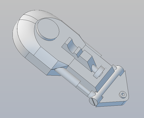
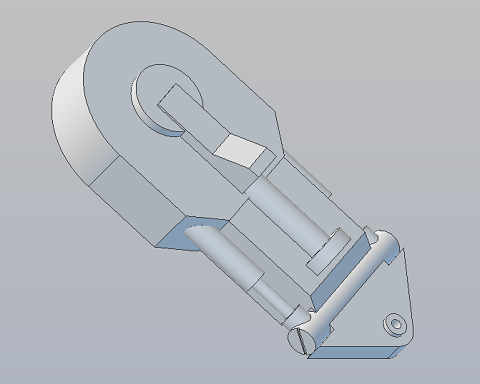
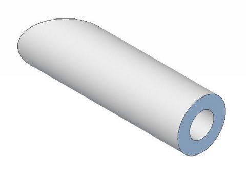
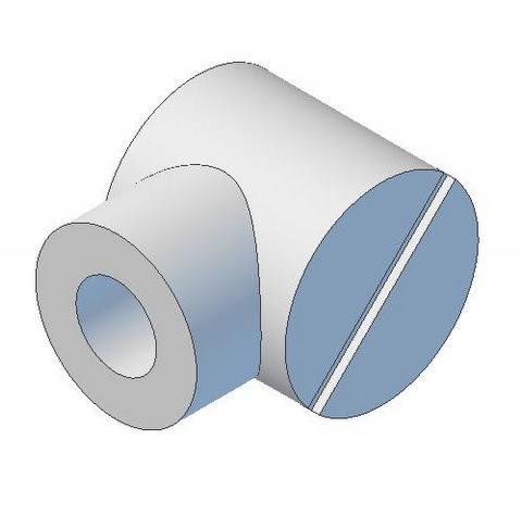
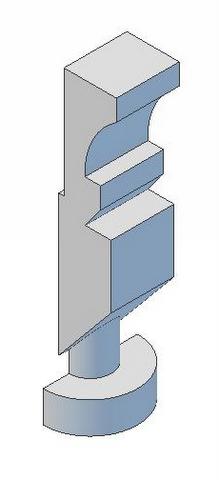
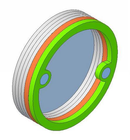
 | The Leg strut is composed of 5 parts. The major three are shown to the left The central component is simply a .625 in dia cylinder. For simplicity, I'm going to cut that from an acrylic tube. The other two parts are round trim pieces that complete the appearance of a cylinder extending across the leg. (see below) The remaining Leg Strut Upper and Lower parts will be resin castings. |
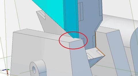
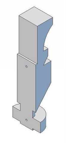
 I've modified the Leg Strut Upper to have a .63 hole in the bottom. | 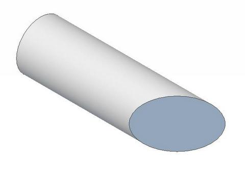 |
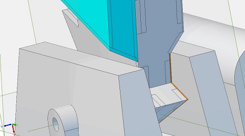
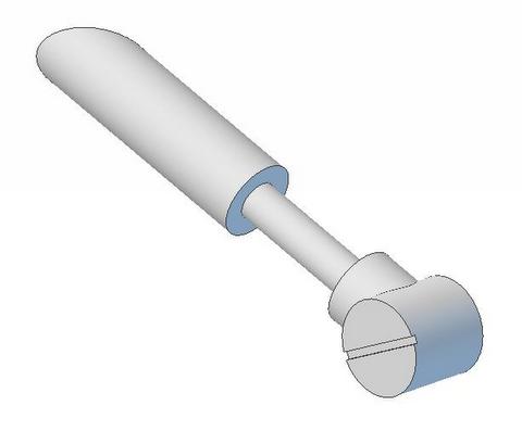
 The Leg Strut Lower is actually 2 pieces. one has a similar .63 hole in it's top face. The Leg Strut Lower is actually 2 pieces. one has a similar .63 hole in it's top face. | The other piece is a CNC Cap, made from .125 styrene, with a .065 channel cut into it's surface. It's assembled to a 1.5in acrylic tube. Rotate the Cap so the channel is in the position you want. 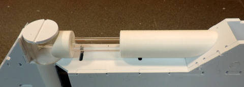 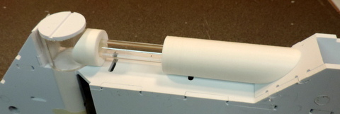 |
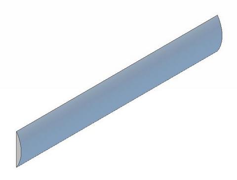 | Left: There are two Leg Strut Round Trim pieces one for each side of the leg. To download the .stl files for these pieces click here |
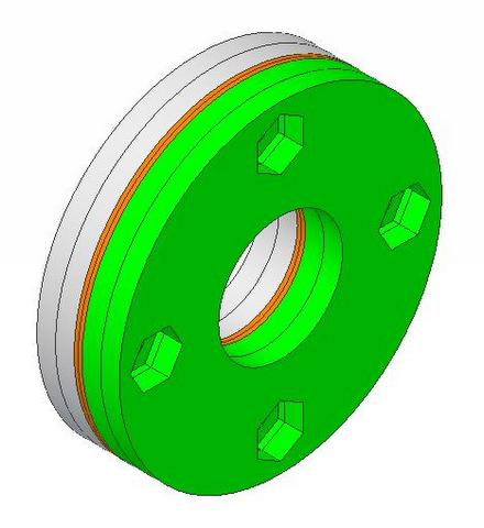
  The Left Leg Applique is shorter than the Right Leg Applique and can be permanently applied to the leg. The blind holes are for alignment while gluing. | 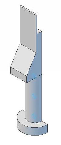 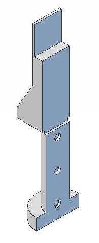 The Right Leg Applique extends over the Leg Shoulder Cover. It is held in place with magnets. |
 Chopper's Shoulder Cover is held in place by a pair of magnets. |  The Leg Frame has a pair of tabs that accept 1/4-20 bolts that are used as magnetic attachment points for the shoulder cover. |
 Choppers Leg Mounting Hub features a set of recess holes for nuts that can hold the hub and the bolts in place while the legs are attached to the frame. | 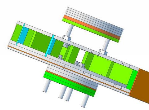 Part of the leg skins have been peeled off so you can get a better view inside to see how the Shoulder Cover and Mounting Hub assemble to the common frame. |
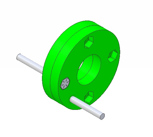 | This
is a special design leg hub to fix the case where the 3D printed frame
was assembled with the left & right uprights in the wrong sides. It's not complete, but can be used as is. The 2 pieces are identical. There are no holes for the bolts to pass thru. Once you determine the correct angle just drill thru. (hint) If someone tells me what the angle should be I'll add the necessary holes. download the .stl part file here. |