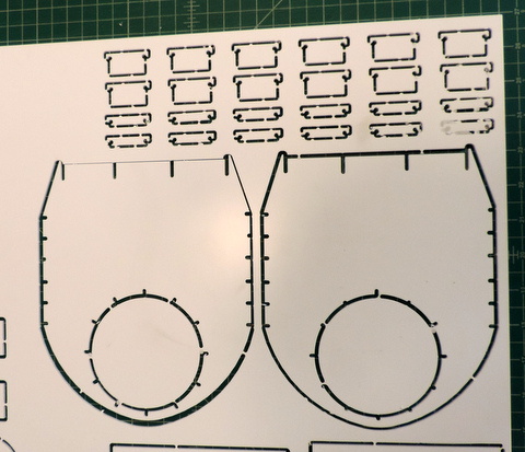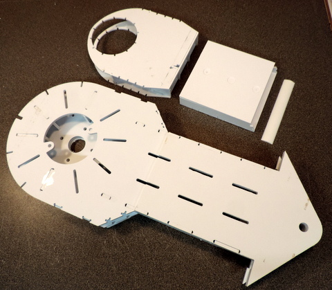
Version 0 Prototype.
Clockwise from the top:
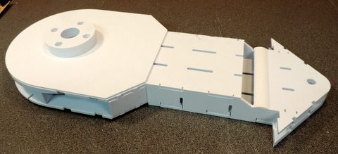
Left Leg top center (non Structural).
Left & Right Leg lower box (non Structural).[missing end cap]
3D printed strut (see Struts below for more detail)
Left & Right Commom Leg Frame (Structural).
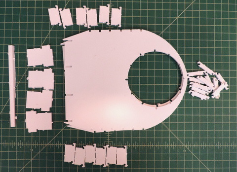
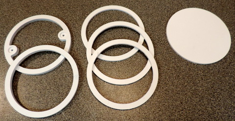
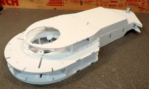
All the pieces are shown without the .040 skins.
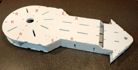
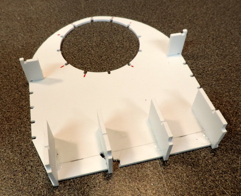
Issues with the fit of the parts kept me from fully populating the box beam structure. R's mark the location of Ribs, E mark the Edge Fillers. [missing angled end cap]
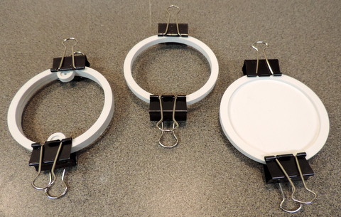
Above: The leg really has none of the intended Box Beam Structure.
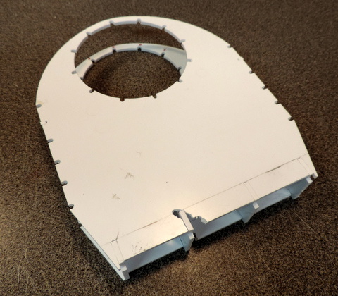
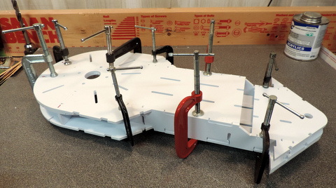
Right: Left Leg assembly without the 3D printed curved top.
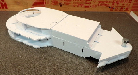
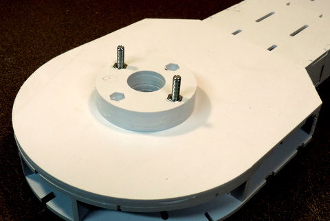
Shown with Shoulder Hub (see below).
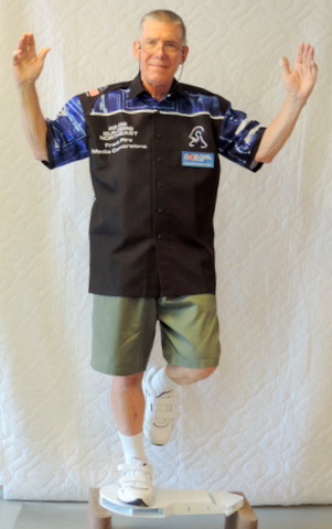
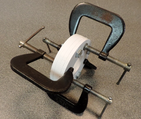
Children. Don't try this at home!
That's 160+ Lbs of weight on a mostly hollow leg assembly.
| Left Leg Top Center |