Computer Interface Arm


Click on the image to open a 3D .pdf version of the design.

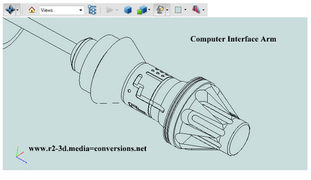
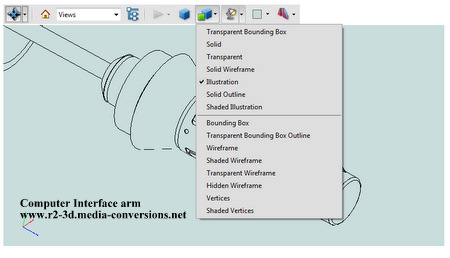
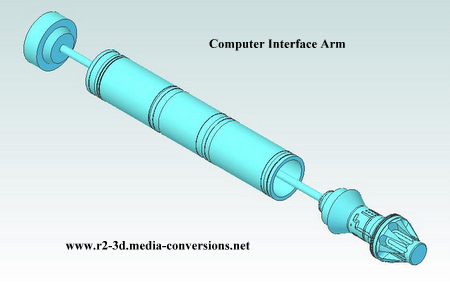
Once you open the 3D .pdf file, you can change the display to "illustration" (bottom left) by using the dropdown list from the top of the screen (bottom right). It makes it easier to see the detail on the front of the interface arm.

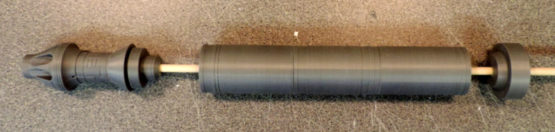
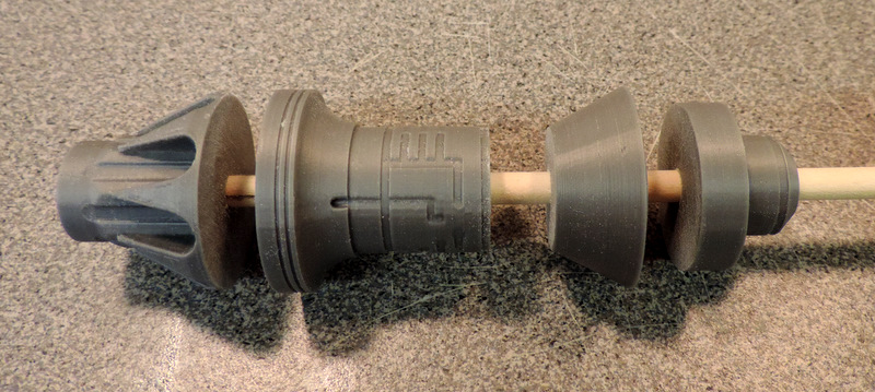
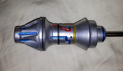
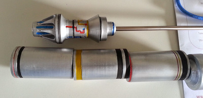
I only have 2 pictures of the arm that I managed to find in the R2BC Galleries under Reference Photos / Tools, Gadets & Accessories. One thing that the drawing files do not show is the alignment of the detail "carving" around the center of the front part with respect to the 8 grooves on the probe tip. If anyone has, or can point me at, a photo of the arm tip that shows the alignment of, for example, the set screw hole, with one of the grooves in the tip, I'd appreaciate it.

You can download models in STEP AP203 (.stp) format in English (inch) units as well as in 3D.pdf format: click here.


To make the arm easier to print I've broken it up into 8 pieces.
the Base - the small piece at the far left

the Tip - broken into 4 parts
from left to right: tip - point, tip - carved, tip - tail a, tip - tail b

the Body - broken into 3 parts
from left to right: body - top, body - middle, body - bottom


I'm supplying only the arm parts. They are designed to mount onto a 1/4 inch rod, or hollow tube.
304 Stainless Steel tubing, .035 wall thickness, is available from Etsy - https://www.etsy.com/listing/198436196/14-304-stainless-steel-round-tube-x-035
Speedy Metals carries tubing in both .035 and .065 wall thickness - http://www.speedymetals.com/c-8276-round-tube.aspx?thickness=0.25
Speedy Metals also carries 1/4 inch rod in both aluminum and steel. You will need more than a 12 in length, 18 in should be more than enough.
If you get your rod at either Lowes or Home Depot bring a caliper with you to make sure they are not oversize. Sanding down an 18 inch rod is a pain!
The tube might be useful if you wanted to put a LED in the tip of the arm and run the wiring thru the tube.
If you do, contact me as I can print a version of the arm tip with a small hole in the end to fit the size of the led you are using.
The Tip parts weigh ~ 1 oz. the Arm Body parts and the base are ~ 3 oz.
At a length of ~12 inches that's about 48 oz-in of torque for the servo that will raise the arm to it's extended position.

Assembly Notes
First, familiarize yourself with the BC Club drawing that the arm design is based on. You can find it at 
Body - Computer Interface Arm.pdf
it's in the groups.yahoo.com/neo/groups/r2builders/files/002-OFFICIAL_BLUEPRINTS/BODY section

As with most 3D printed parts, the holes in the parts are undersized. Enlarge them with a 1/4 inch drill and, depending on the shaft you are using, some careful additional sanding migh be required. I used a piece of sandpaper rolled around a small (~ 1/8 inch) rod.


These parts have been edge lit to emphasize the small surface defects.
To fill in the surface grain from the 3D printing you might want to sand lightly and prime.
Take care not to fill in the small details on the tip with the primer!
Consult the R2BC forum threads on painting 3D parts for guidance.

Parts shown here for the Arm Body are not polarized.
You can assemble the center section backwards so observe the orientation.

front of the arm to the left, front section has double narrow ring
middle section with the double wide ring ro the rear.
future versions of the parts will have a small polarizing ring so they only go together one way!

While you can clamp all of the pieces of the arm together and glue them at one time I find that I get better alignment by only gluing one pair of parts together at a time. The glue tends to act as a 'lubricant' causing the joints to slide. If you are gluing multiple joints and have to move one you are most likely going to disturb the others.

These were sent to me by Carlos G!  Nice Job on the finishing and thanks for the Pix!


Home