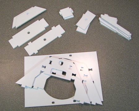
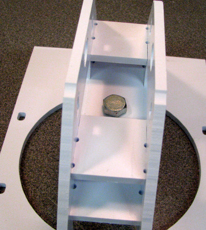
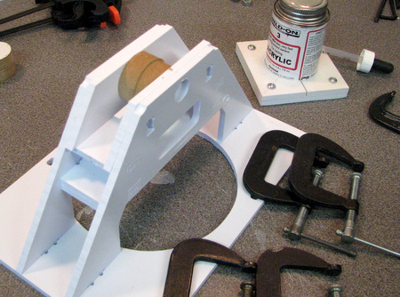
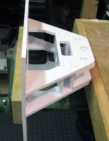
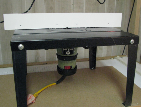
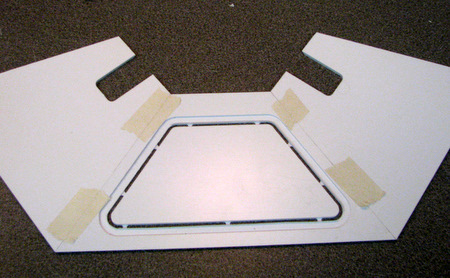
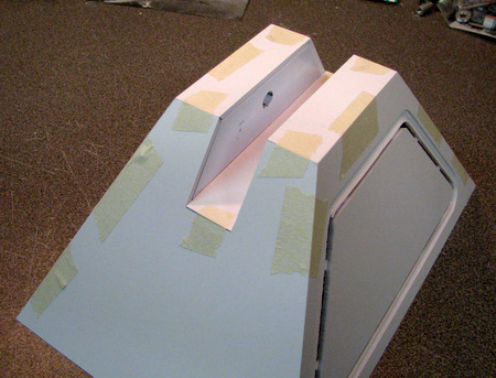
The Center Foot Assembly

There are several phases to the Center Foot Assembly. We'll start with the inner structural components, then move to the outer foot shell. There is some mechanical work to do and then those two assemblies get fitted together to make a complete center foot. Finally the Center Foot is mounted to the Center Ankle! Parts are described on the mc.center.foot drawing available here as a .pdf file.

Structural Assembly
Foot Shell Assembly
Mechanical Work
Fitting the two Assemblies Together
Finishing Touches

 Structural Assembly: The first step is to separate all of the parts from the sheets they were machined from, remove the tabs and flash, if any.


Left: We begin with the two main plate frame parts and the two top cross spacers then turn the assembly over and insert the upper bottom cross spacer.


When you have all the parts fitted and clamped flow some Weldon 3 into the joints from both top and bottom of the frame. You want these joints to be really strong! Use the bottom plate for alignment, be careful not to get cement into the bottom plate joints (yet).
Set the assembly aside for a while to let the glue harden.

use a 5/16-18 bolt to hold the lower bottom cross piece in position

The bottom part will have a shoulder cut into it so that the stem caster seats properly when it's installed. make sure the cut is visible from the bottom of the foot!

flow some cement between the upper & lower cross plates then quickly bolt together
With the bolt holding the parts in position, clamp tightly for a strong joint.
Set the assembly aside for a while to let the glue harden.


I'm using two pieces of 1/2 in MDF to make sure the channel stays at a 1 inch spacing during gluing. Put the spacers in between the Partial Plate pieces.

Flow cement in thru the openings in the main plates. then clamp everything for tight joints.

If you get softened plastic oozing out from the joints just clamp the assembly in a vise and file the joint smooth . No need for perfection at this point as there will be more filing later when we join the Structural assembly with the Shell.


Here I'm mating the frame with the bottom plate. I found it easiest to flow Weldon 3 into the joint and then quickly clamp the foot in a vise until the glue was dry.

In the picture to the Left it's the lower of the two joints that's being glued.


The final part of the assembly is to put in the side ribs.

If you are having problems getting a tight joint you might want to file the edges. The tab as been made shorter to help with the fit.

Clamping is difficult because of the angles. Really heavy duty rubber bands or clamping (upside down) in a vise at the points where the notches are both work.

Above: Once the joints at the top are dry turn the assembly over and glue the joints at the bottom of the foot.

Left: I used a combination of weights and clamping to get a good joint.
This Completes the Center Foot Structural Assembly.

Foot Shell Assembly:
I decided to cut the bevels for these parts using a router set up on a router table with an edge guide adjusted to get the right depth of cut. When you get these parts they will have been already beveled and then taped back into the part panel for shipping. Here's what the process looks like.


Parts separated from panel.

Above: Edges of parts marked so that I cut the bevels in the right places!
Right: the router setup used for cutting.

Above: The parts after cutting.
Right: you are still going to have to do some hand filing to sharpen up the corners on the end panels.

Note: do not remove the inner parts on the side panels.

Place the panels on a flat surface,  bevels down,  and tape the edges.  Make sure the top and bottom corners line up.

Work your way around until you have all of the panels taped together. Then fold the pieces in together to make the pyramid shape.

Use the two top pieces to square off your pyramid.

With the panels taped together, it's time to do a test fitting to see how the foot shell fits over the structural frame.
Left: There will be some small gaps in the fit. We will be filing the frame for a better fit to the shell later on.

The center pieces in the side panels will be removed after we glue up the shell. right now they are adding strength to the sides of the shell.


Once you are happy with the alignment of the foot shell parts, put more tape over the joints (don't remove the existing tape!).

We will be gluing from the inside and you don't want any glue to leak out.

To glue the shell I used Weldon #16 . Make sure you don't get too much glue on the top pieces. It will interfere with the fit of the structural frame.

So, remove any excess glue before it hardens! (And try to do a neater job than I did)
Not shown: For additional strength I added a bead of Squadron Green putty on the inside of the foot shell joints where the side panels meet the end panels. Stop just short of the top of the foot shell so the putty does not interfere with the fit of the shell against the ribs. (you can see the putty in the 4th picture in the Fitting the two Assemblies Together part of the directions below.

Mechanical Work: Unlike most of my styrene designs, the Center Foot has a number of mechanical components to it that require some working to adjust them to our purposes. See the Mechanical Parts page for a description and supplier information.


This is the set of parts used to hold the center foot to the center ankle. It's a 3/8 x 1 inch spacer threaded to take two 3/8 x 1/4 shoulder bolts.
Note: if you don't want to buy a 5/15-18 tap just for this project send me email. I'll tap one for you and include it with your order.

When I bought my 5/16-18 taps they came as a set of 3 - you want the "plug" tap if you buy only one. Put a tape marker at 1/2 inch.

Clamp the spacer using a V block. Using the plug tap there will be a small gap between the threads from each end.

The threaded part of the 3/8 inch shoulder bolts is 1/2 inch long. That's too deep for the 1 inch spacer we are using and trying to tap threads all the way to the midpoint would be difficult. It's just easier to grind off about 1/8 in. from the end of the bolts.

The shorter bolts fit tightly. If you don't have a grinder, a coarse sanding disk in a drill also works.


I'm going to use magnets to hold the foot shell side panels in place. There are spaces for K&J Magnets on the panels and the side ribs. In this picture I'm using silicone adhesive. This is my first adventure with magnets. I've since switched to E6000 cement.

Once the magnets on the side panels are in place you need to glue the ones on the ribs.

Since they are not marked (north/south) simply let two magnets pick their mating sides.

Above: Once you have mated magnets, mark them, and the mating ribs, in different colors.
Right: Glue the color coded magnets in place.

Drill or file the 3/8 in holes for the stem caster and the shoulder bolts so the mating parts fit easily.

Don't forget this step, once the foot shell is in place the mounting holes for the shoulder bolts are almost inaccessible!

Fitting the Foot Shell to the Structural Frame:
Begin the 
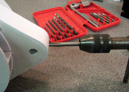
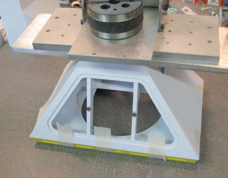
fitting process by filing the ribs smooth and flat.

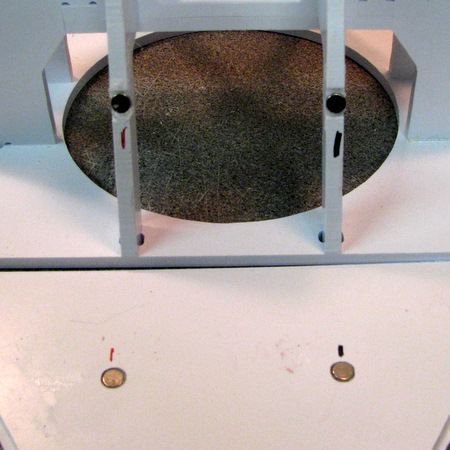
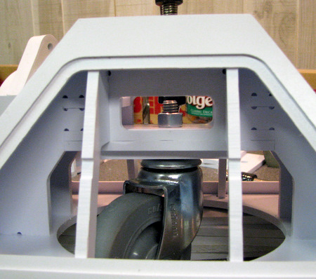
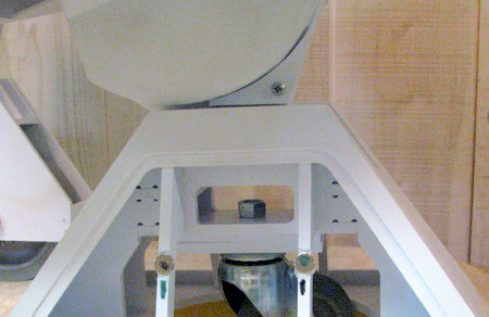
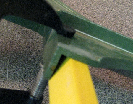
Then clamp the shell to the frame and examine the fit of the bottom plate.

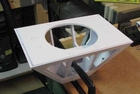
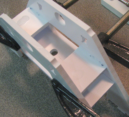
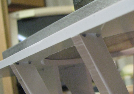
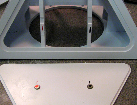
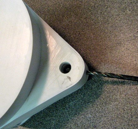
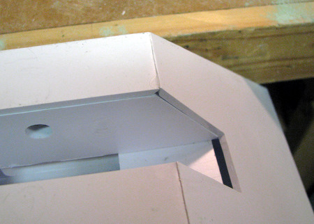
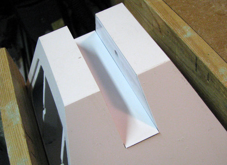
You are looking to have the surface of the bottom plate of the frame and the angle cut edges of the foot shell flush with each other. If the frame is high there will be a gap where the apron joins the bottom of the foot.
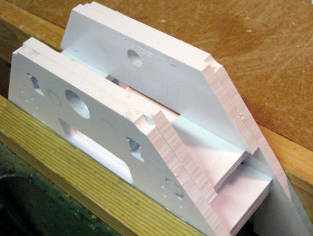
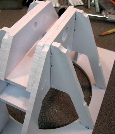
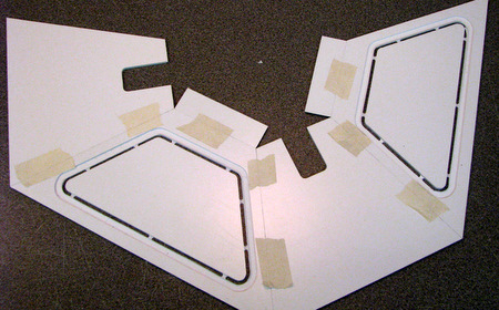
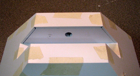
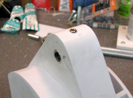
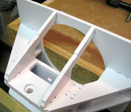
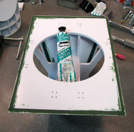
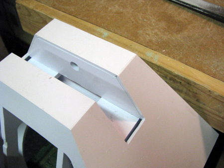
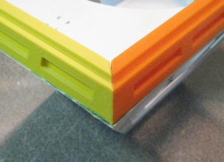
You can see the bead of Squadron Green Putty I added to the foot shell joints here.

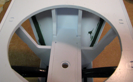
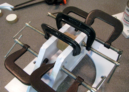
Once you are happy with the fit of the shell and frame, drip Weldon #16 glue down the surfaces where the ribs and the shell are in contact.
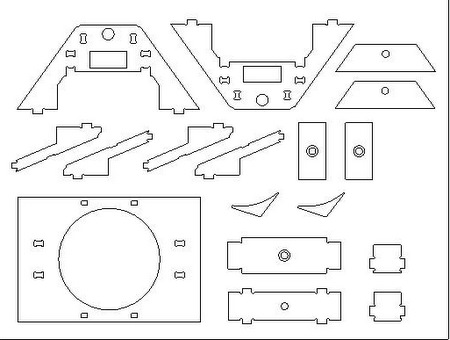
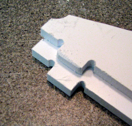
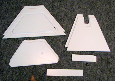
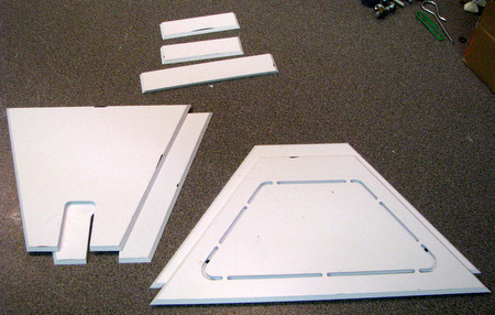
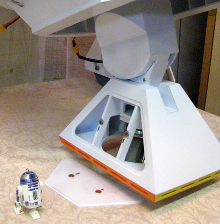
After looking at the CNC cut versions of the apron I decided that 3D printed versions would be both much better looking and much easier to fit in place (no filing of angle joints)

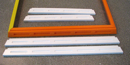
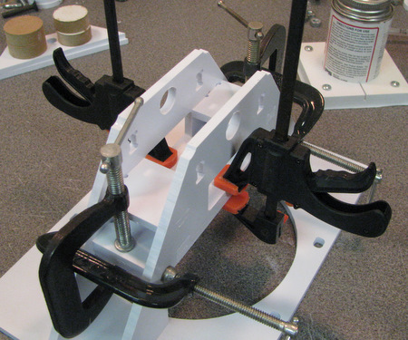
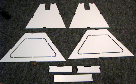
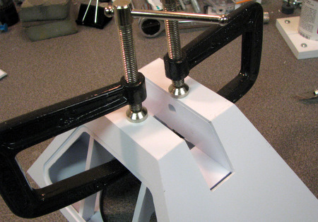
The apron is printed in 4 pieces and must be put together much like a picture frame. I used a corner clamp to hold the parts mostly because I had it.

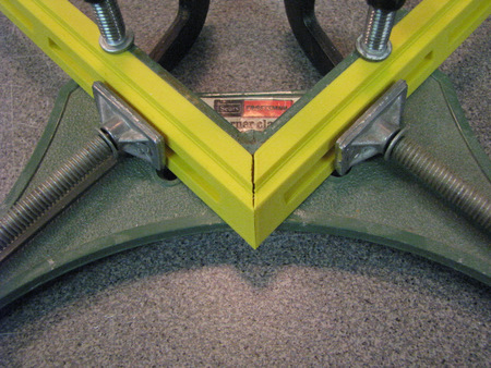
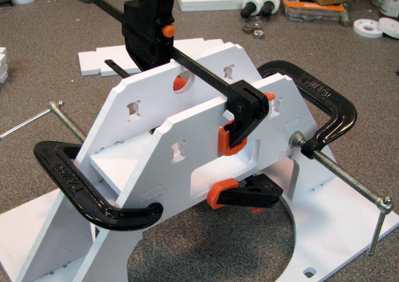
My corner clamp only worked because the height of the clamps frame matched the height of the apron and I could use a C-clamp to hold the apron parts in position. If you don't have a corner clamp just put the pieces on a flat surface to glue the corners together. Use a square to make sure the joints are at right angles.

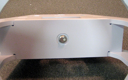
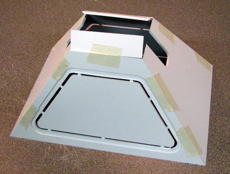
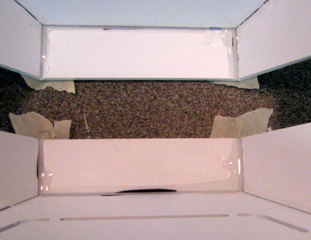
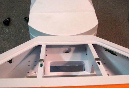
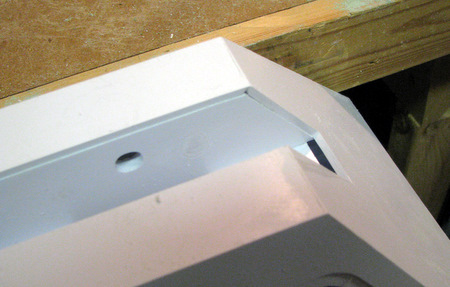
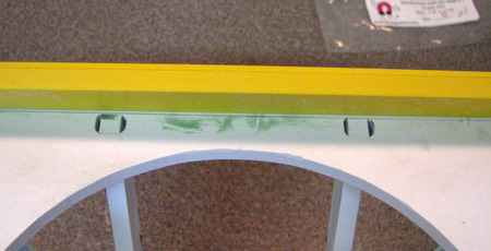
I used Squadron Green Putty to fill in the gap between the bottom plate and the edges of the foot shell. Doing so will give the apron parts a larger area to bond to.

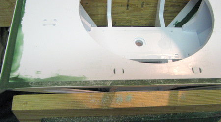
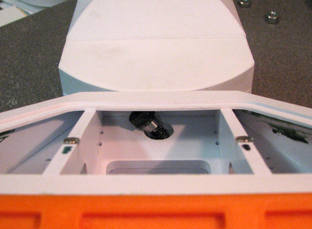
File off the high spots and any excess putty that is on the bottom plate. I had to use two applications of the putty to get a flush surface.

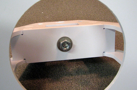
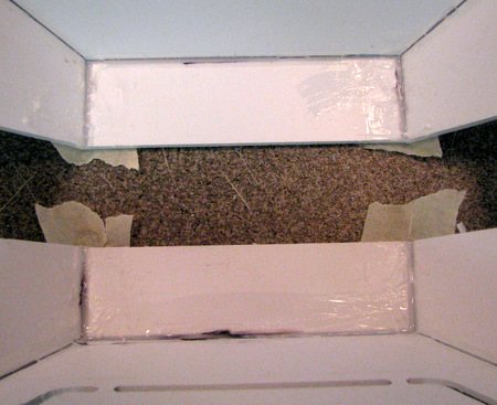
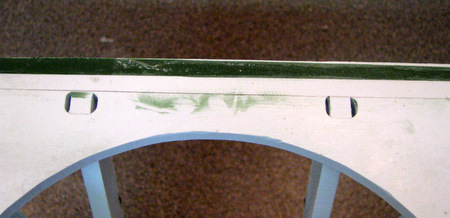
Some of the foot shell edge will start to show up as you file. Don't remove too much of the edge!

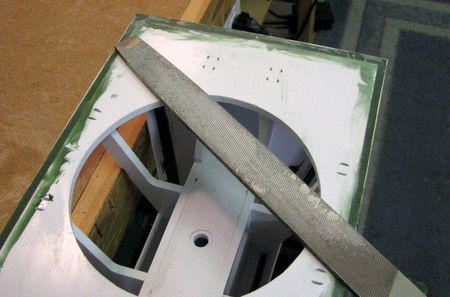
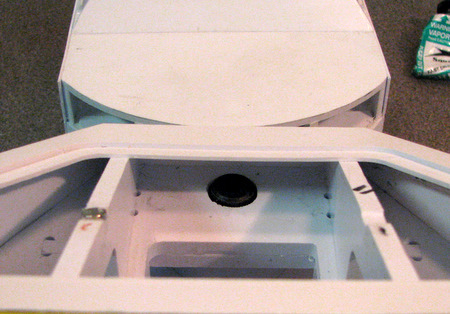
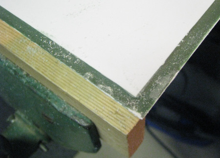
I used a large flat file and spanned across the bottom plate to make sure I didn't file off too much of the edges.

While the file is out, take a moment to neaten up any of the other foot shell edges that might need some touch-up.

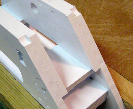
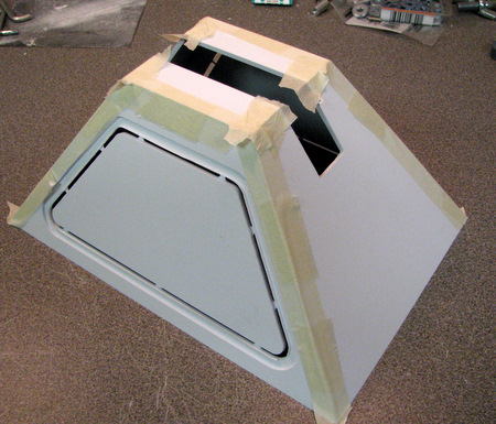
Here I've smoothed off the joint at the top of the shell

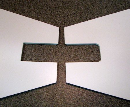
You can also clean up the joint between the structural plates and the end plates of the shell. (the vertical edges of the slot).

You can also glue the cover plate in place and trim it's edges.

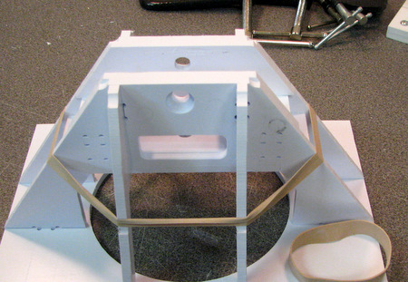
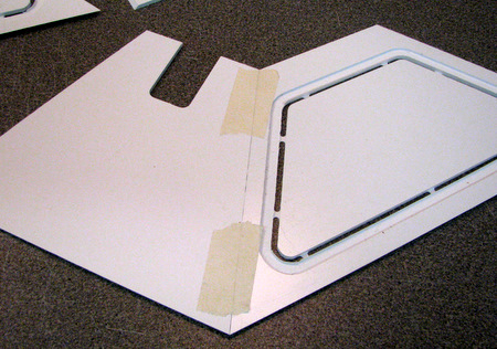
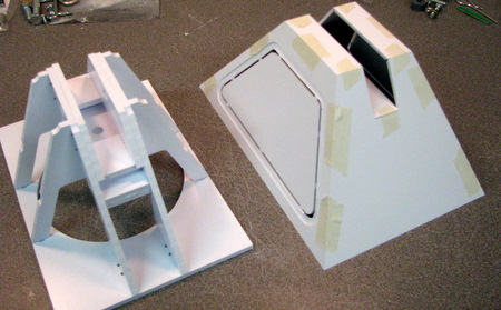
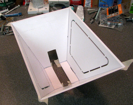
When the apron glue joints are dry, put it in place on the bottom of the shell and draw a pencil line on the inside.

Use the pencil line as a guide and apply a generous bead of Weldon #16 to the bottom plate.

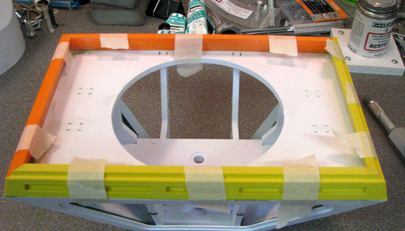
Set the apron in place and tape it to hold it in position.

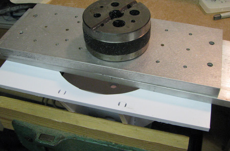
I turned things over and added weights on top while the glue dried.

The resulting joint will need some filing to even off the joint.

Finishing touches: Installing caster, modifying ankle, mating foot to ankle, ankle locks.

File a flat in the threaded spacer. You don't want to take a chance that one of the bolts will freeze up and you can't unscrew it because it's spinning around in the ankle.

Drill a hole thru the bottom of the center foot.

And tap so you can insert a setscrew

make sure the setscrew engages the flat on your spacer.

I could have used a shorter set screw, but it's hidden in any case.

install the caster in your ankle. it's shown here with only one spacer which will reduce the ground clearance  from 1.5 in to 1.28 in

Fitting the center foot to the center ankle is tedious because of the tight space. First make sure you can see the threaded spacer in the center of the hole.

place the shoulder bolt and tilt it into the hole

gradually tighten the bolt until the shoulder drops into all the way into the mounting hole.

you only need to go finger tight with the shoulder bolts. the channel in the center foot takes all of the side force. the bolts only carry a vertical load.
Left: final step is to install the ankle locks onto the center ankle. I put one in from each side.


Congratulations, you've got a completed Center Foot for your R2!


Home