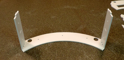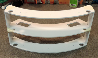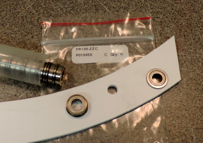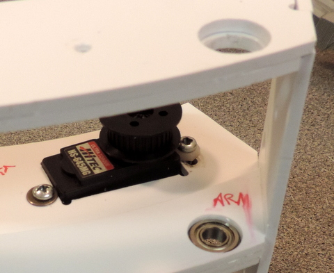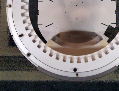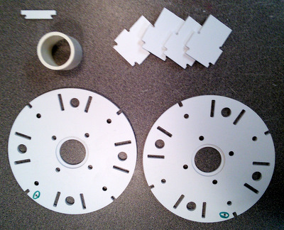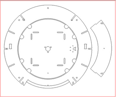
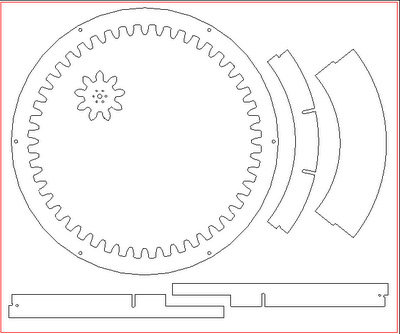
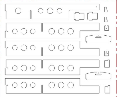
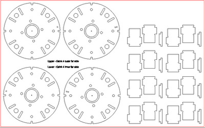
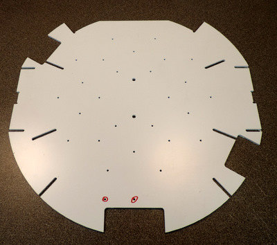
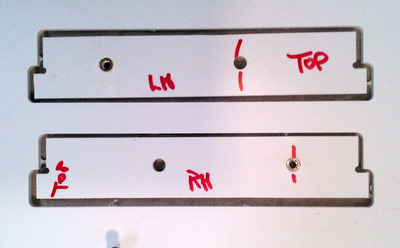
Ring4, Core4, Utility Arm Ring (upper). Ring4 now has mounting holes for the Rockler bearing while the Core4 plate has holes for a dome motor and slip ring mount.
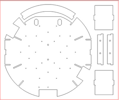
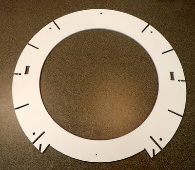
Core2 & Core3, Under Shoulder Rings, Door Ring (top), and Door Ring (middle) 05/16/20 - The PVC Core 2,3,4 panels have been replaced by the Tab Core panels. The instructions that follow have not been updated. (follow the link!)

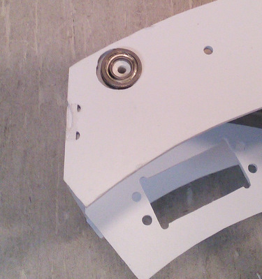
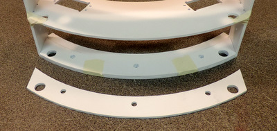
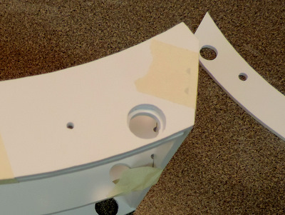
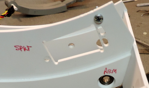
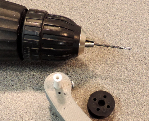
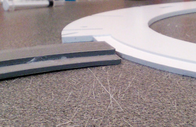
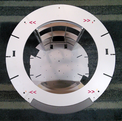
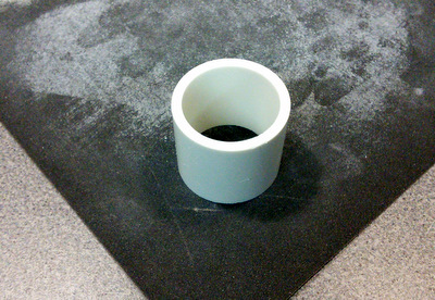
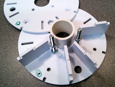
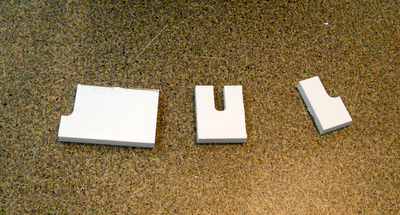
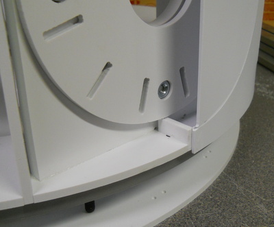
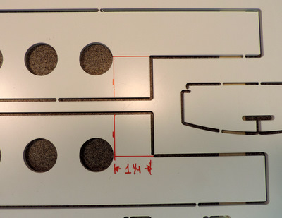
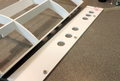
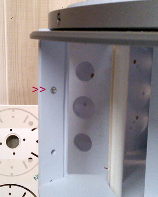
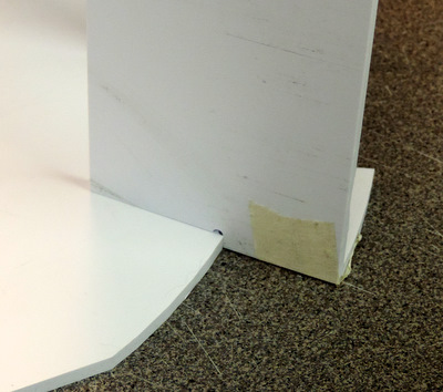
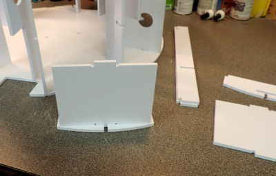
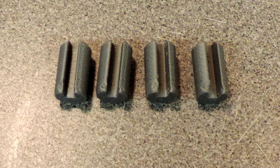
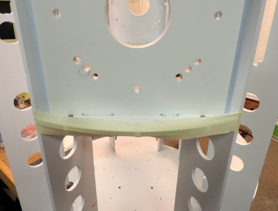
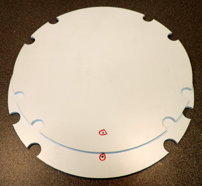
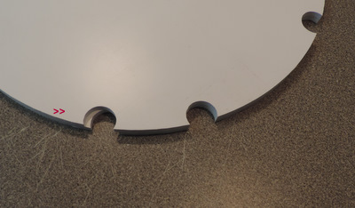
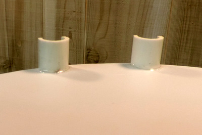
This is the MC variant of the Large Data Port. The lip on the upper part mates with the notch on Ring4.

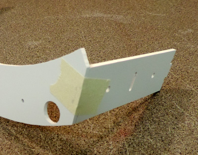
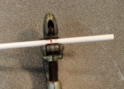
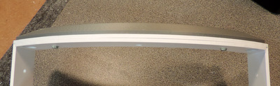
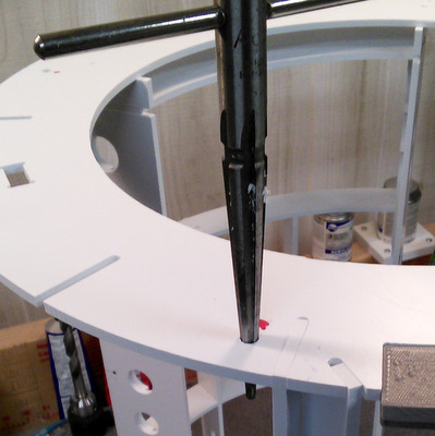
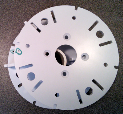
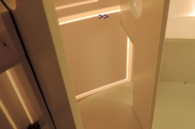
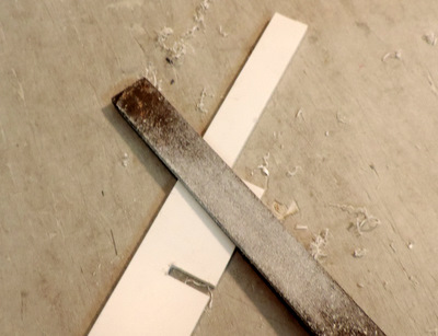
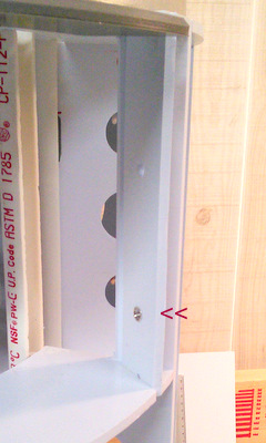
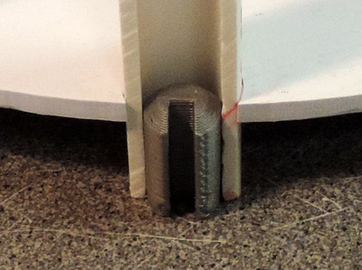
here's a better view of the notch in ring4 shown above.
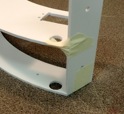
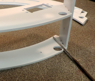
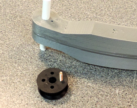
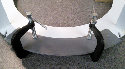
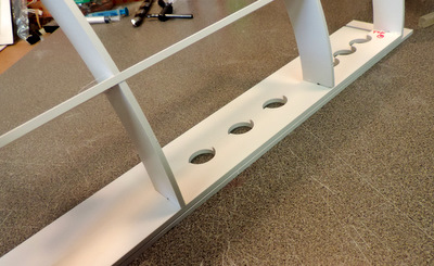
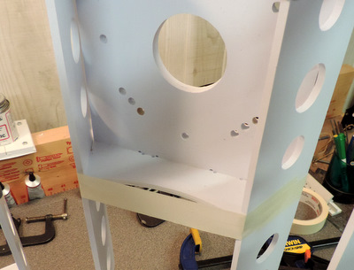
this feature should be facing down (into the body of the droid)
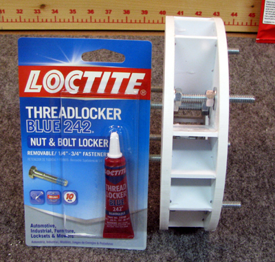
NOTE!! - you should hold off on installing your LDP until after you have mounted your skins to the frame. Otherwise the skin mount gets more complicated.
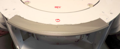
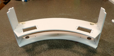
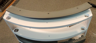
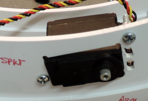
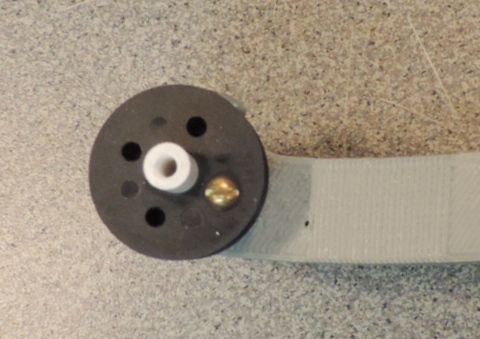
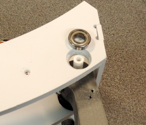
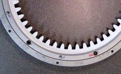
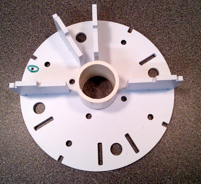
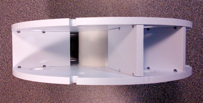
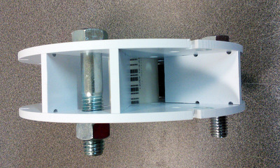
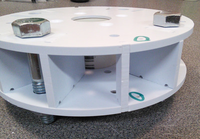
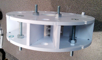
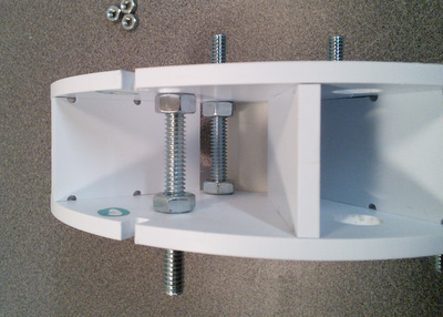
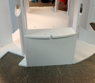
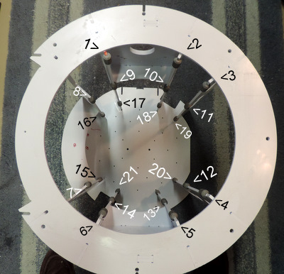
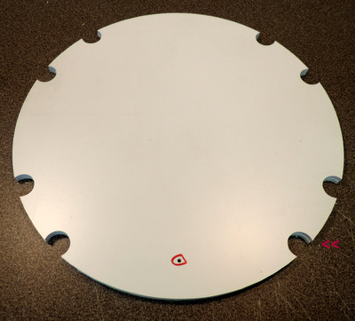
Left: top view of LDP installed on Ring4
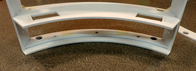
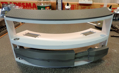
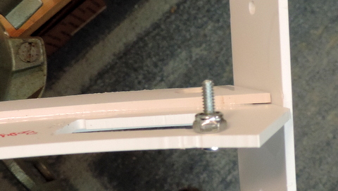
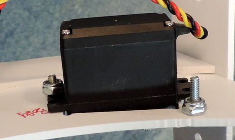
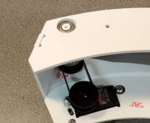
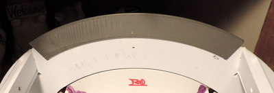
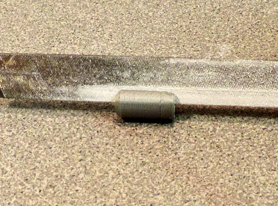
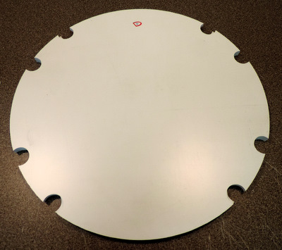
Above: bottom view of LDP
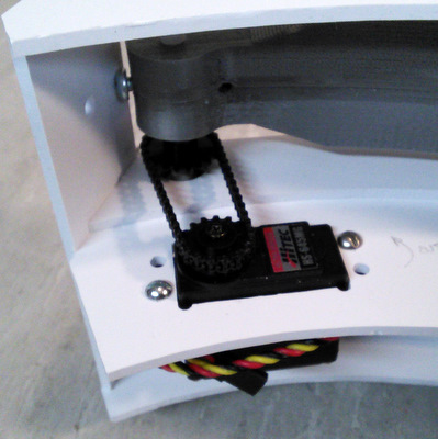
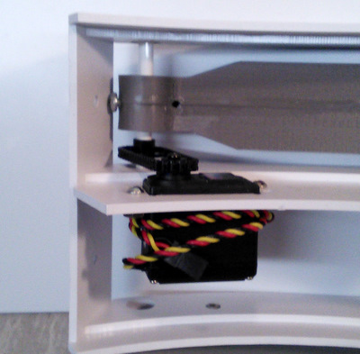
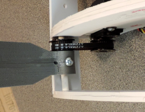
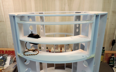
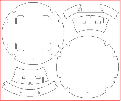
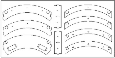
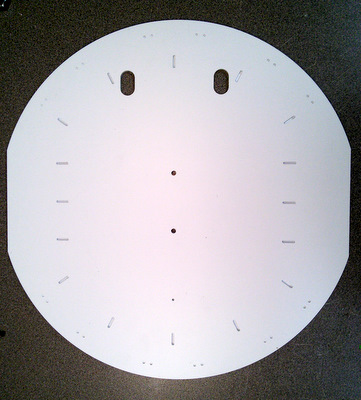
Dome Motivator, door ring middle, rear door ring, inner door ribs
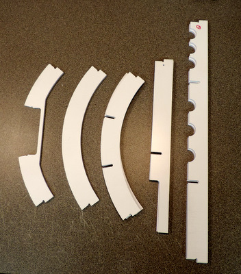
Ring1 Frame Bottom (the extra holes are for gluing to Ring0), Top Door Ring, Ankle Slice Panels, Utility Arm Box Ribs
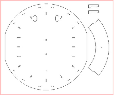
Ring0 (also serves as the skirt bottom), Utility arm ring (lower). Rib slots end with Ring1 so it's not necessary to fill in the joints.
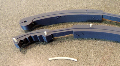
The two small parts are the rear door keys. See rear door frame assembly for more information.
[02/10/16] Do not Glue Ring0 in place until after you mount the skins. Having it removable will make the skin mounting easier!
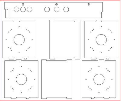
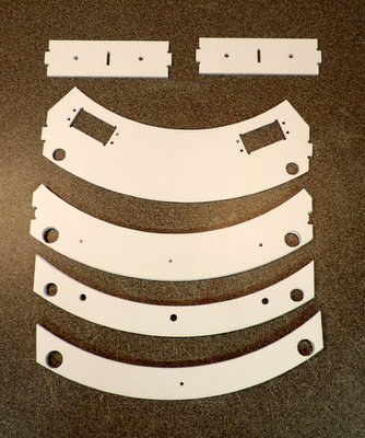
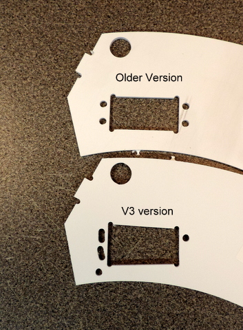
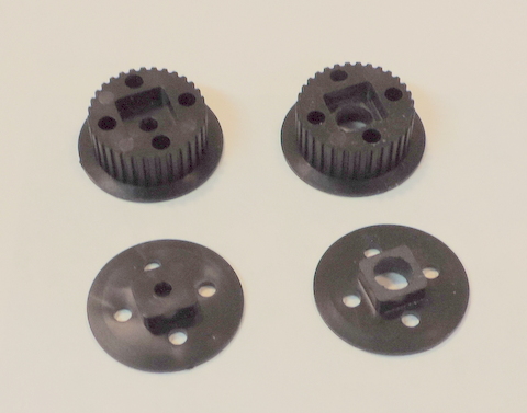
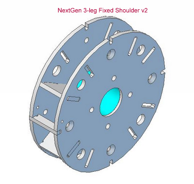
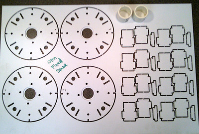
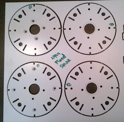
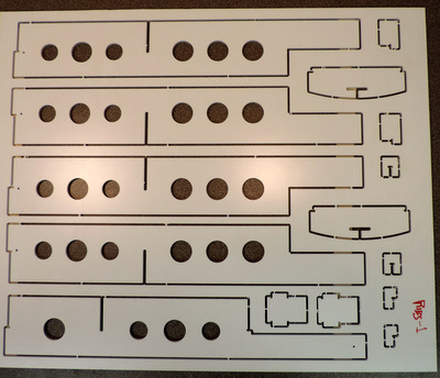
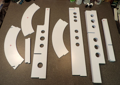
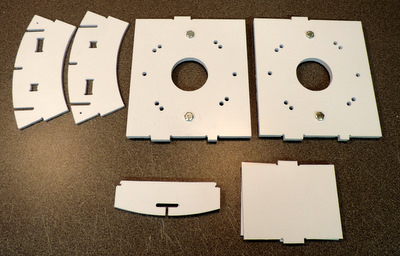
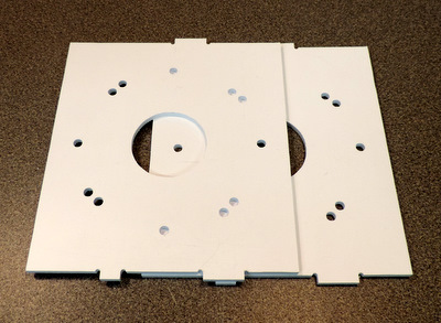
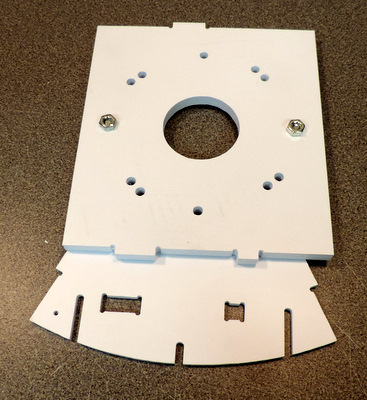
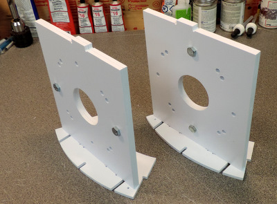
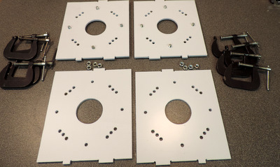
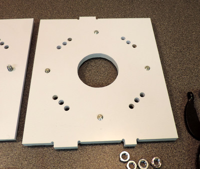
Plates - shoulder (4), core mounting plates (1), and a rear door rib. The shoulder plates now have mounting holes for both 2-leg and 3-leg configurations.
Ribs1 - ankle slice rings and skin attachment points
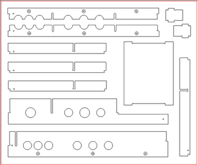
Ribs2 - and the second Core mounting plate.
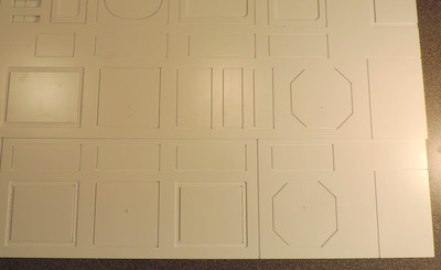
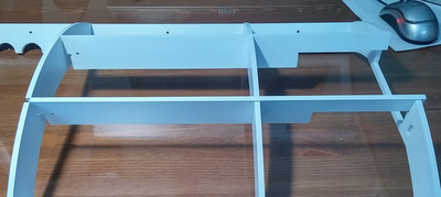
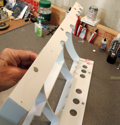
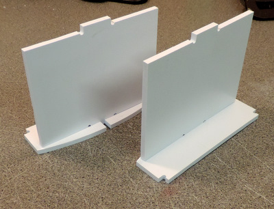
Above: these are the skin attachment points. shown above in the Ribs1 panel they are not discussed here in the frame assembly.
Right: they are installed in the droid's "armpit" and are used to anchor the end joints of the 1/2 wrap engraved skins.
you'll find more information on the web pages that talk about mounting the engraved skins.
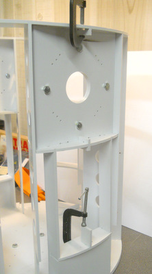
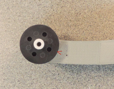
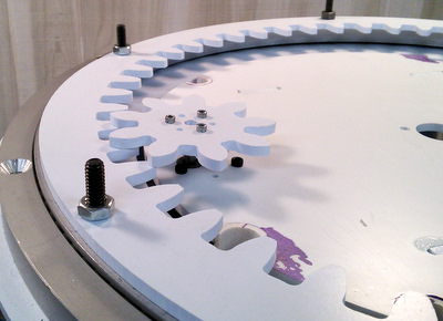
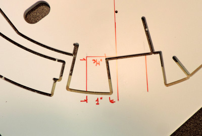
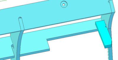
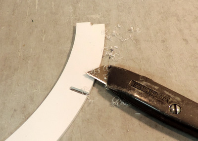
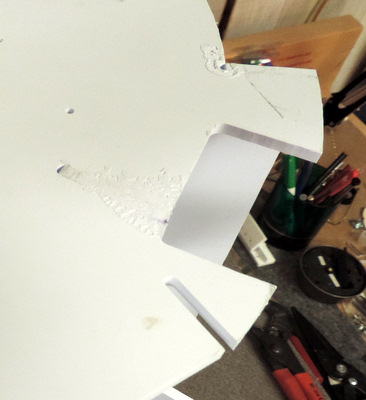
Here is how the skin attachment points work. Only one problem. They don't leave enough clearance around the Fixed Shoulder. [The large holes in the shoulder just happen to fit over the 1/4-20 bolts]
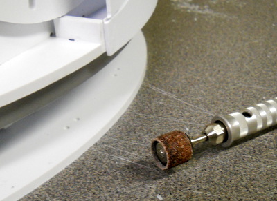
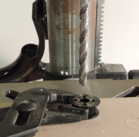
If you have already glued the attachment points in place you can use a dremel tool to grind off enough to give you clearance around the Fixed shoulders. Remember they get wrapped with a layer of .040, so you'll need that much on both top and bottom.
CS:R Shoulder Hub
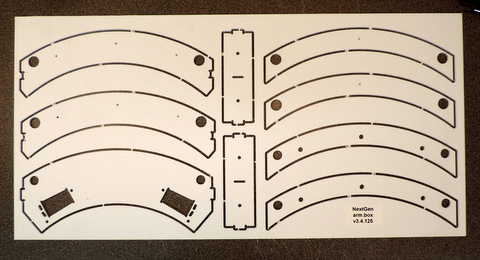
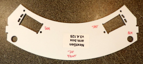
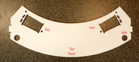
NextGen Frame Utility Arm Box (.125 thick)
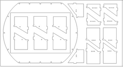
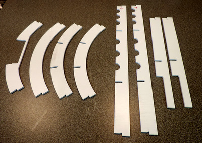
NextGen Frame Skirt Parts (.125 thick)

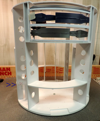
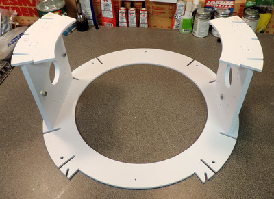
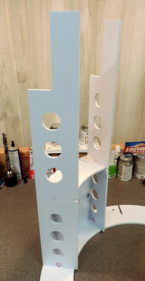
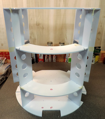
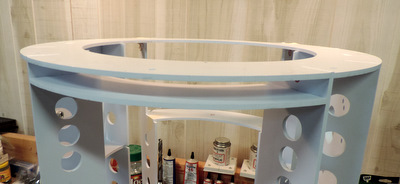
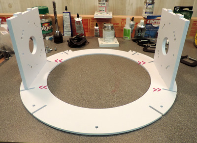

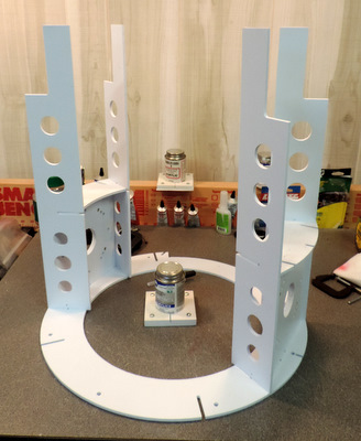
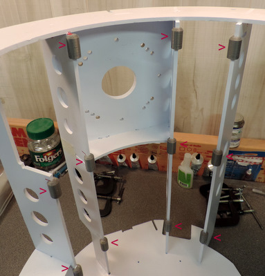
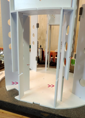
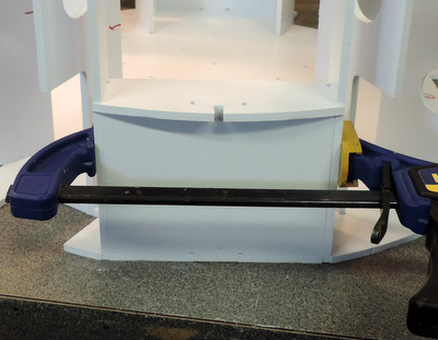
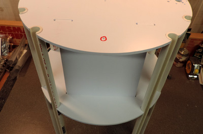
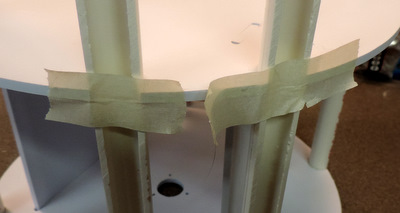
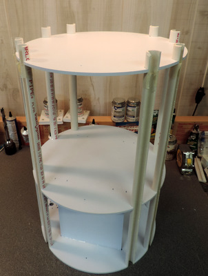
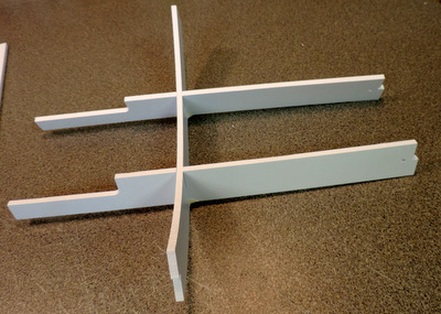
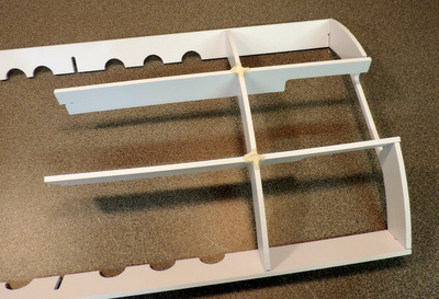
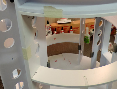
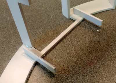
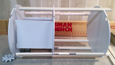
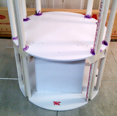
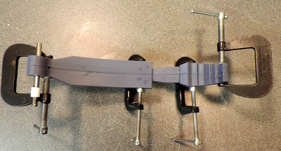
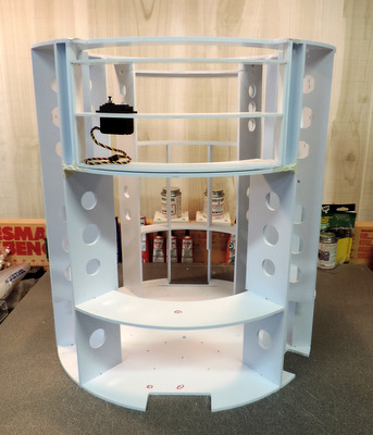
 First,
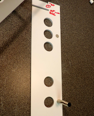
note that I've bolted the ring0, skirt bottom, onto the
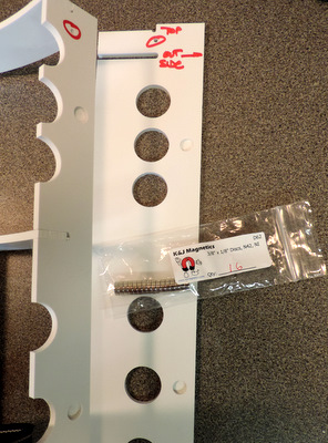
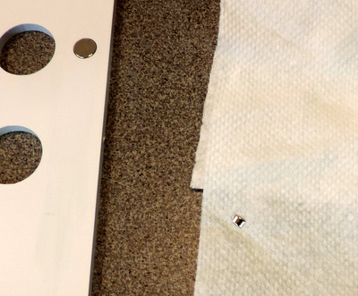
bottom of the frame. with the magnets holding the two outside ribs in
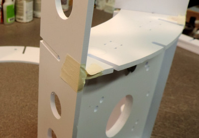
place, insert the top and bottom rings of the door frame and tape in
position.
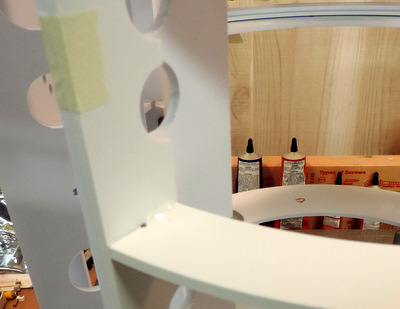
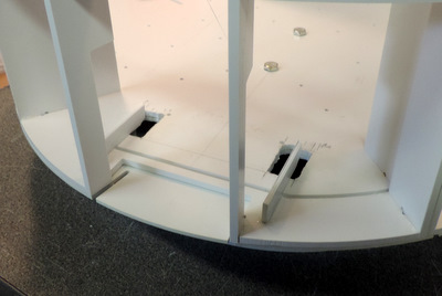
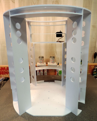
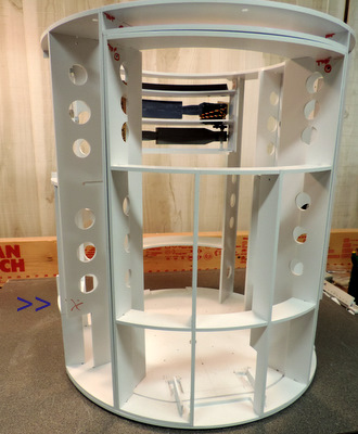
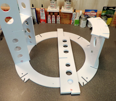
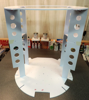
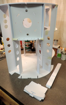
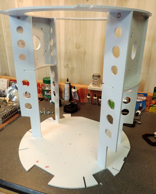
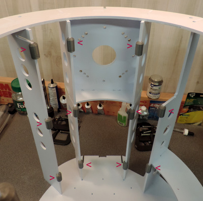
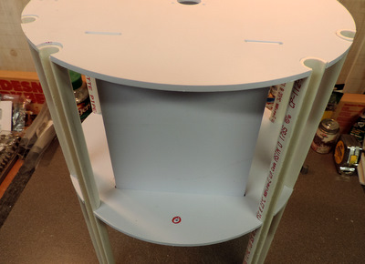
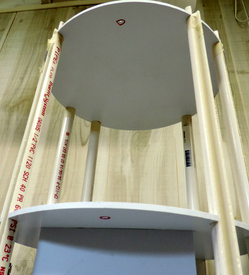
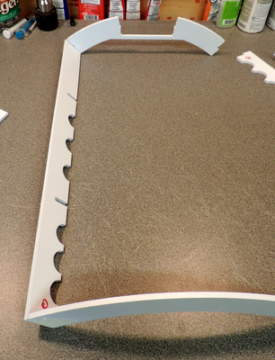
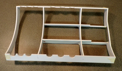
First,
note that I've bolted the ring0, skirt bottom, onto the
bottom of the frame. with the magnets holding the two outside ribs in
place, insert the top and bottom rings of the door frame and tape in
position.