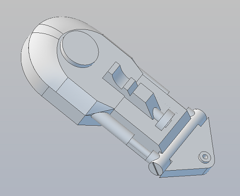
The
remaining (older) drawings show the internal structure.
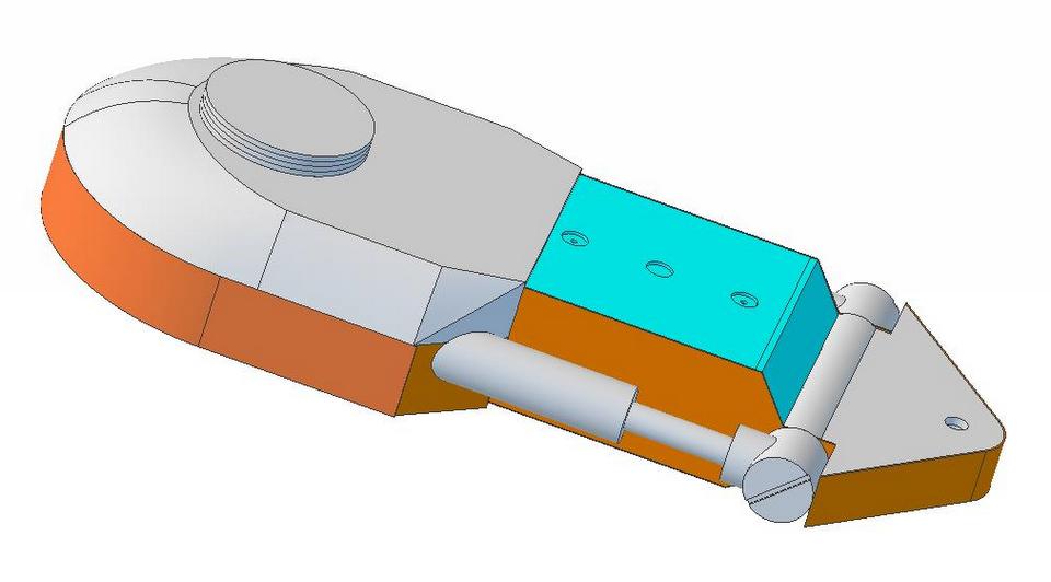
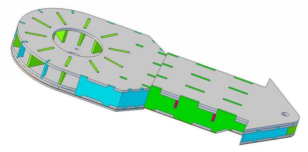
Leg
Frame design is a structural component common to both legs. In this
image it's wrapped with .040 skins (2 layers on the curved top portion).
|
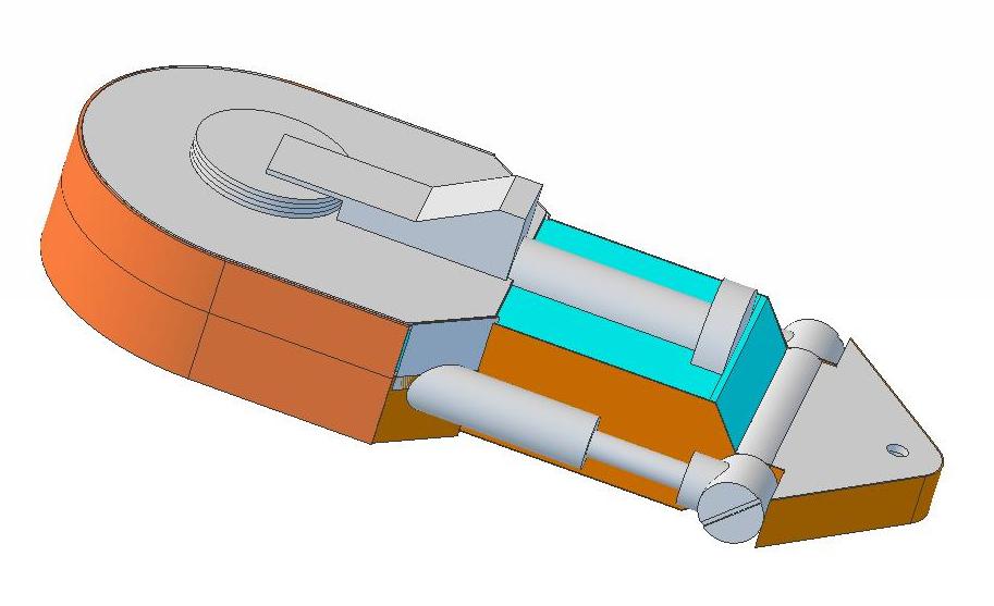
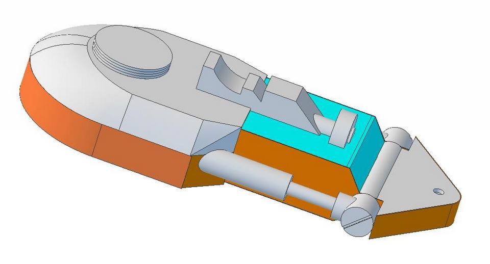
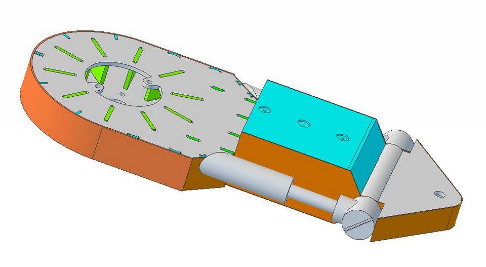
Here we have peeled off the .040 skins. The blue color
components are .125 thick non-structural parts of the design. The
balance of the parts are all .1875
|
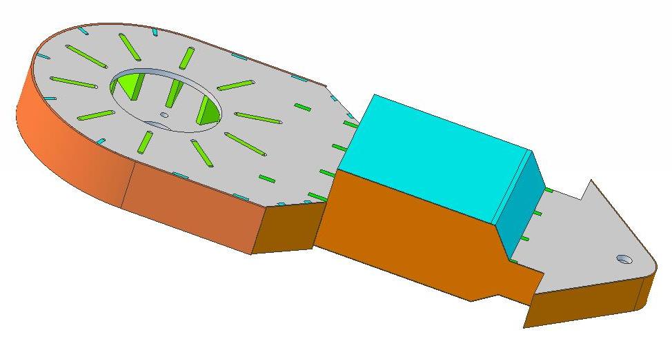
For
strength, the leg has 3 layers of .1875 styrene, with an additional
layer in the area where the leg bolts to the body. As a result of the
change in thickness of the leg where it is mounted to the foot, there
are 2 layers in the top inner section and 2 layers in the bottom outer
section of the leg.
|
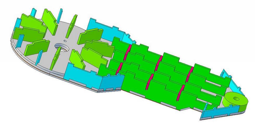
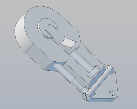
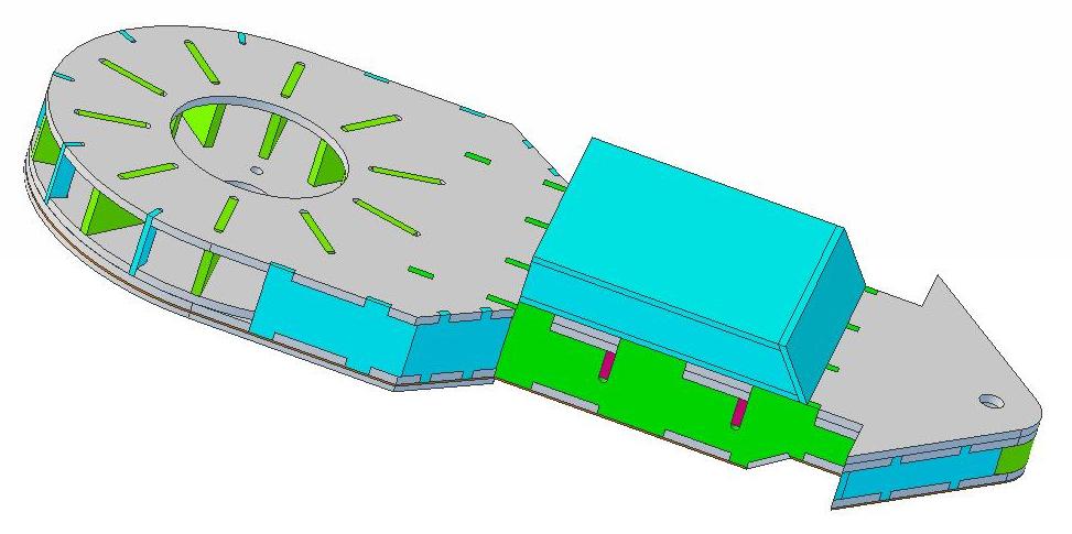
With the outer layer peeled off you can see the box
beam ribs that run top to bottom as well as ribs that radiate around the area
where the leg bolts to the body. The center channel between the
shoulder and the foot is unobstructed for wiring between the body and
the foot. Not shown is the hole at the bottom of
the legs for the wires to exit. It's location is dependent on which
side of the body the leg is built for. |
What's still to be done: It's my first pass at
designing parts to be cast. More than likely I've done some things that
will make casting the parts more difficult. I'm waiting to get feedback
on the parts I'm proposing to have made,
Design 'cleanup' - the bevel edges on most of the parts that have
them are cut to the angles dictated by the design. Bevel cutters are
restricted to the available set of 15,30,45 degree angles. The bevels
will be modified so that the edges meet where needed.
Please ask
questions, make comments & suggestions that you think
might improve the design.
Contact me using: fpirz (at)
media (dash) conversions
(dot) net |